|
550 602 02 |
||||
|
|
||||
|
Visual VIGO – Graphics and Data Acquisition
IntroductionVisual VIGO is a Windows based application program, used to visualise and operate process plants, factory automation, building management systems, etc. on a PC (SCADA functionality). The PC can be connected on-line locally, or remotely via a LAN, direct MODEM access or Internet connection, through the VIGO Fieldbus management system and the P-NET Fieldbus.
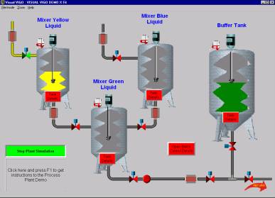
A process plant is visualised by designing one or more work floors, where machines, equipment and instruments can be placed. The operator is able to “walk” through the factory by opening “doors” to the different work floors and departments of the Factory. The different machines and instruments can be opened for studying internal details. Visual VIGO is based on an object-oriented principle, where Visual VIGO components can contain other Visual VIGO components, each of which can contain other components etc. Visual VIGO components are placed on the work floors, and can be used to illustrate a complete working area, an individual machine, the internal details of a machine, an actuator, a sensor, a control function, a value, a set point, a data recorder etc.
The way a Visual VIGOcomponent is presented to the user involves the use of images, multimedia items, and help information. Visual VIGO components can take different states. These states can be represented by using a set of chosen images, and if required, include sounds and visual effects. The images could originate from a picture taken with a camera, from a scanner or be generated by any standard drawing program or computed by Visual VIGO components.
Multi-media effects are based on standard .avi and .wav files generated by the user or chosen from a variety of prepared sources. If required, Help information can be generated by the designer using standard text preparation facilities and associated with a particular component.
Features· Ease of use for designers as well as operators. · Visual VIGO runs within the VIGO environment, and as such, Visual VIGO components can inherit the functionality of VIGO. · Visual VIGO components can be customised by system integrators. · Visual VIGO components can be developed by third parties, and added to existing systems without compilation. · The principle of using the right-hand mouse button in VIGO, where a selected channel or variable shows a menu with the relevant tools or properties, is the same in Visual VIGO.
Ease of UseOne of the main goals of Visual VIGO has been that it will be so easy to use, that the need for reading the manual would be minimised. This has been achieved by adopting the same familiar methods for editing elements as used within other standard Windows applications. As an example, the following functions can be found in right-hand mouse button menus: Cut, Copy, Paste, Delete, Group, Order, Edit of properties and Help.
In Visual VIGO, the need to deal with file and folder names has been reduced to as low a level as possible. The designer is only required to define names for two types of folder:
· A complete Visual VIGOdesign is saved under one folder name. · A Component box, together with all its components, is saved under another folder name.
Visual VIGO is designed to be utilised at different levels for:
· Operators using a Visual VIGO design created by others. · Designers that create new Visual VIGO designs based on standard components. · Designers that create new components by grouping a set of standard components and then copying them to the Component box. · Component designers that create new components with a new appearance, but having the same functionality. For example, a Valve component can be converted into a Pump component just by exchanging the images. · Component programmers that develop new component functionality.
Additional components having a new functionality can be developed using Delphi from Borland, using the Visual VIGO class library.
Visual VIGO keeps track of which components are visible, and which are hidden behind other work floors. In this way, time wasted in reading variables over the network to update values on the screen that are not visible, can be avoided. The consequent bandwidth requirement for the network is therefore heavily reduced. This also leads to the fact that invisible components can release memory allocated to store images, and thus reduces the overall memory requirement. The VIGO objects can be released when the component is hidden, and as such can, for example, close Modem connections.
Component Box A Visual VIGO design is created by copying Visual VIGO components into the design from a Component box or from another Visual VIGO design. All components are independent.
New components can be copied into the Component box, without the requirement of compiling any programs: just copy and paste the components. Adding new Visual VIGO components in this way makes it possible to introduce new Visual VIGO components without the risk of changing the functionality of existing components.
Visual VIGO components can be easily exchanged between different Visual VIGO users. This is done by first copying the components to be exchanged into a Component box. From the Component box, all components can be packed into one file, and sent by email. Visual VIGO components are automatically given unique identities, to avoid accidental overwriting of components having the same file name.
The Component box and its contained components are not required when the design is being used in Run mode.
Component Tree
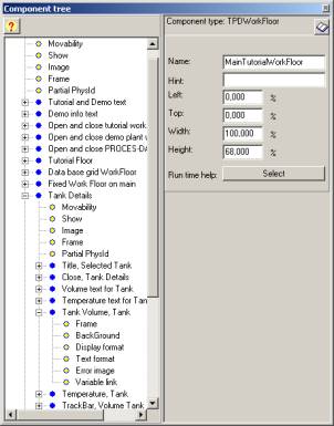
From a right-hand mouse menu, the Component Tree can be opened to inspect and change the configuration of Visual VIGO components. Such configuration could relate to properties of the Visual VIGO components or parameters in a related I/O channel in the hardware.
A Visual VIGO Design has a hierarchical structure, where components hold other components. This structure can be visualised as a tree, starting with the main Work floor as the root, followed by branch components holding other components etc. The Component tree window shows this structure together with the editable properties of a selected component. A component can be “selected” by clicking the component in the Visual VIGO Design or the icon of the component in the Component tree. When it is selected, it is highlighted in the tree, and the component in the Visual VIGO container is shown with boundary markers.
Data AcquisitionVisual VIGO provides powerful facilities to log real time data and display current and historical measurements in a graphical or tabular form. Data is either logged and stored on a PC or extracted from logged data held in a remotely sited P-NET controller or DPI. Using the collection of Data Acquisition components provided, enables display and analysis of specific groups of logged variables by scrolling, zooming and performing accurate cross-hair measurement.
Related topics |
|
||