|
550 709 01 |
|||||||||||||||||||||||||||||||||||||||||||||||||||||||||||||||||||||||||||||||||||||||||||||||||||||||||||||||||||||||||||||||||||||||||||||||||||||||||||||||||||||||||||||||||||||||||||||||||||||||||||||||||||||||||||||||||||||||||||||||||||||||||||||||||||||||||||||||||||||||||||||||||||||||||||||||||||||||||||||||||||||||||||||||||||||||||||||||||||||||||||||||||||||||||||||||||||||||||||||||||||||||||||||||||||||||||||||||||||||||||||||||||||||||||||||||||||||||||||||||||||||||||||||||||||||||||||||||||||||||||||||||||||||||||||||||||||||||||||||||||||||||||||||||||||||||||||||||||||||||||||||||||||||||||||||||||||||||||||||||||||||||||||||||||||||||||||||||||||||||||||||||||||||||||||||||||||||||||||||||||||||||||||||||||||||||||||||||||||||||||||||||||||||||||||||||||||||||||||||||||||||||||||||||||||||||||||||||||||||||||||||||||||||||||||||||||||||||||||||||||||||||||||||||||||||||||||||||||||||||||||||||||||||||||||||||||||||||||||||||||||||||||||||||||||||||||||||||||||||||
|
|
|||||||||||||||||||||||||||||||||||||||||||||||||||||||||||||||||||||||||||||||||||||||||||||||||||||||||||||||||||||||||||||||||||||||||||||||||||||||||||||||||||||||||||||||||||||||||||||||||||||||||||||||||||||||||||||||||||||||||||||||||||||||||||||||||||||||||||||||||||||||||||||||||||||||||||||||||||||||||||||||||||||||||||||||||||||||||||||||||||||||||||||||||||||||||||||||||||||||||||||||||||||||||||||||||||||||||||||||||||||||||||||||||||||||||||||||||||||||||||||||||||||||||||||||||||||||||||||||||||||||||||||||||||||||||||||||||||||||||||||||||||||||||||||||||||||||||||||||||||||||||||||||||||||||||||||||||||||||||||||||||||||||||||||||||||||||||||||||||||||||||||||||||||||||||||||||||||||||||||||||||||||||||||||||||||||||||||||||||||||||||||||||||||||||||||||||||||||||||||||||||||||||||||||||||||||||||||||||||||||||||||||||||||||||||||||||||||||||||||||||||||||||||||||||||||||||||||||||||||||||||||||||||||||||||||||||||||||||||||||||||||||||||||||||||||||||||||||||||||||||
|
PD 662 Redundancy Channel (channel 1)
Registers in Channel:
RegNo 0: ActualPort
ActualPort shows which of the RS485 port is actually being used. 0 = neither. 1 = RS485 Port 1 2 = RS485 Port 2
RegNo 9: ChConfigThe ChConfig variable is a record of the following type:
ErrorMax defines how many frames with errors that are allowed within 16 consecutive frames received at the port, before the port is set to Inactive (and Errorstate). To set the port back to a non-error state, the port has to receive less than ErrorMax-2 frames with error within 16 consecutive frames. If ErrorMax is set to 2 or less the port has to receive 16 frames without errors, before the port is set back to a non-error state. ErrorMaxcan be set to a value from 0 to 8.
PreferredPort can be used to select which of the RS485 ports is to be the one used if both ports are in a non-error state. 0 = Automatic 1 = RS485 Port 1 preferred 2 = RS485 Port 2 preferred
EnableNotification: Notification can be enabled in the following cases:
RegNo 11: RS485Port1InfoRegNo 12: RS485Port2InfoRegNo 13: LightlinkInfo
Registers 11 to 13 all have the same structure:
ErrorFlagsAct: describes which errors are detected. It is updated when/if the port is put in inactive state.
ErrorFlagsHist is set if the port is set to Error state (more than ErrorMax errors in the last 16 frames) by the PD 662. A Master (e.g. a PD 601) can reset the bits if the corresponding bits in ErrorFlagAct are not set.
ErrorFlagAct bits are set when the PD 662, due to errors, sets the port to Error state. All types of error represented within the last 16 frames, will have their corresponding bit set. All bits in the register are reset when the PD 662 changes a port from Error state to Non-error state. A Master cannot write to the register.
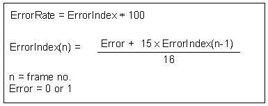
ErrorRate is calculated by this formula:
The Notification bit is only set if the Error rate ascends.
ErrorCounter
ErrorCounter is a record where each error flag has a counter. After a reset of the PD 662, the counters are initialised to zero. Every error detected by the PD 662 will increment the error counter, including errors detected in the Non-error state. The counters increment to a max. of 255 and cannot revert to zero before a master (e.g. a PD 601) has reset the counter.
FrameError is incremented on any frame error.
ChecksumError is incremented on any checksum error.
BadPNETFrame is incremented on any bad P-NET frame.
LineError is incremented on any line error.
RegNo 14: GuidEach channel in an interface device consists of a unique guid.
RegNo 15: ChError
There are two sets of error bits, actual and historical. The actual error bits reflect the current situation and will automatically follow any change. The historical error bits reflect the history and have the purpose of holding sporadic errors. The historical error bits are set together with the corresponding actual bits. They remain set after a read, so each individual bit must be cleared by setting it to false. Only the bits where the corresponding actual bit is false can be cleared. See summary for how ChError.His can be cleared in particular M36 slave modules. The “His data error” bit in the P-NET response is set if any historical bit is true. The “Act data error” bit in the P-NET response is reflecting the validity of the data in the response. Overload, electrical error or an error in other registers involved in calculating the result gives “Act data error”.
The following two bits will cause Act error In the P-NET response on access to all variables.
Bit 0 Program_storage_fault is set TRUE if the self-test finds an error in the program memory.
Bit 1 RAM_storage_fault is set TRUE if the self-test finds an error in the data memory (RAM).
Bit 2 InternalReset is set TRUE if a reset is caused by a power failure, or if the power has been disconnected (only a His error).
Bit 3 ExternalReset is set TRUE if a reset is caused by writing 255 to Reset, via P‑NET (only a His error).
The following bits are set TRUE if the self-test finds an error in the data memory (EEPROM) for the variable. EEPROM fault is only set at power-up. If the corresponding variable is accessed, Act error in the P-NET response is set. This error can occur if the power disappears when writing to EEPROM. A rewrite to the variable might solve the problem.
Bit 7 EEPROM_Error in ChConfig
|
|
|||||||||||||||||||||||||||||||||||||||||||||||||||||||||||||||||||||||||||||||||||||||||||||||||||||||||||||||||||||||||||||||||||||||||||||||||||||||||||||||||||||||||||||||||||||||||||||||||||||||||||||||||||||||||||||||||||||||||||||||||||||||||||||||||||||||||||||||||||||||||||||||||||||||||||||||||||||||||||||||||||||||||||||||||||||||||||||||||||||||||||||||||||||||||||||||||||||||||||||||||||||||||||||||||||||||||||||||||||||||||||||||||||||||||||||||||||||||||||||||||||||||||||||||||||||||||||||||||||||||||||||||||||||||||||||||||||||||||||||||||||||||||||||||||||||||||||||||||||||||||||||||||||||||||||||||||||||||||||||||||||||||||||||||||||||||||||||||||||||||||||||||||||||||||||||||||||||||||||||||||||||||||||||||||||||||||||||||||||||||||||||||||||||||||||||||||||||||||||||||||||||||||||||||||||||||||||||||||||||||||||||||||||||||||||||||||||||||||||||||||||||||||||||||||||||||||||||||||||||||||||||||||||||||||||||||||||||||||||||||||||||||||||||||||||||||||||||||||||||