|
551 299 02 |
|
||||||||||||||||||||||||||||||||||||||||||||||||||||||||||||||||||||||||||||||||||||||||||||||||||||||||||||||||||||||||||||||||||||||||||||||||||||||||||||||||||||||||||||||||||||||||||||||||||||||||||||||||||||||||||||||||||||||||||||||||||||||||||||||||||||||||||||||||||||||||||||||||||||||||||||||||||||||||||||||||||||||||||||||||||||||||||||||||||||||||||||||||||||||||||||||||||||||||||||||||||||||||||||||||||||||||||||||||||||||||||||||||||||||||||||||||||||||||||||||||||||||||||||||||||||||||||||||||||||||||||||||||||||||||||||||||||||||||||||||||||||||||||||||||||||||||||||||||||||||||||||||||||||||||||||||||||||||||||||||||||||||||||||||||||||||||||||||||||||||||||||||||||||||||||||||||||||||||||||||||||||||||||||||||||||||||||||||||||||||||||||||||||||||||||||||||||||||||||||||||||||||||||||||||||||||||||||||||||||||||||||||||||||||||||||||||||||||||||||||||||||||||||||||||||||||||||||||||||||||||||||||||||||||||||||||||||||||||||||||||||||||||||||||||||||||||||||||||||||||
|
|
|
||||||||||||||||||||||||||||||||||||||||||||||||||||||||||||||||||||||||||||||||||||||||||||||||||||||||||||||||||||||||||||||||||||||||||||||||||||||||||||||||||||||||||||||||||||||||||||||||||||||||||||||||||||||||||||||||||||||||||||||||||||||||||||||||||||||||||||||||||||||||||||||||||||||||||||||||||||||||||||||||||||||||||||||||||||||||||||||||||||||||||||||||||||||||||||||||||||||||||||||||||||||||||||||||||||||||||||||||||||||||||||||||||||||||||||||||||||||||||||||||||||||||||||||||||||||||||||||||||||||||||||||||||||||||||||||||||||||||||||||||||||||||||||||||||||||||||||||||||||||||||||||||||||||||||||||||||||||||||||||||||||||||||||||||||||||||||||||||||||||||||||||||||||||||||||||||||||||||||||||||||||||||||||||||||||||||||||||||||||||||||||||||||||||||||||||||||||||||||||||||||||||||||||||||||||||||||||||||||||||||||||||||||||||||||||||||||||||||||||||||||||||||||||||||||||||||||||||||||||||||||||||||||||||||||||||||||||||||||||||||||||||||||||||||||||||||||||||||||||||
|
GPRS Channel
Registers in GPRS channel:
RegNo 0: PINCode
This register holds the PIN Code of the SIM card. If the string is empty, it is assumed that no PIN Code is required. This is the default setting.
RegNo 1: ConnectionProfile
AccessPointName The name (URL) of the access point to connect to. The cell phone company provides the name of the access point. Example: "internet.t-d1.de". AccessPoint can also hold the IP Address and TCP Port directly. Example: "187.188.189.190:1023"
Username The name of the user. The cell phone company provides the user name.
PasswordThe password of the user. The cell phone company provides the password.
DNSServer The DNSServer1 and 2 hold the IP address of 2 different domain name servers, which are used by the PD 664 to translate, for example, AccessPoint into an IP address. The cell phone company provides the DNSServer address(es).
RegNo 2: TCPServer
ServerNodeAddress This field holds the node address used when connecting to the server.
ServerNetID This field holds the NetID used when connecting to the server.
ServerName1, ServerName2 These fields hold the name or IP address of the TCP Server to which this module automatically tries to connect following a reset. If both ServerName1 and ServerName2 are empty, no connection is attempted.
Example: tcpserver.proces-data.com
The default TCP Port number is 34380. Alternatively, another TCP Port number can be specified, for example: tcpserver.proces-data.com:32000
The 3rd option is to enter the IP address together with the TCP Port number, like this: 80.163.183.190:10000
If the server can be reached by means of both domain name and IP address, it is recommended that both are entered.
Example: ServerName1: tcpserver.process-data-com:10000 ServerName2: 80.163.183.190:10000
ServerPassword This field holds the password used when connecting to the GPRS server. This field is "Write only".
RegNo 3: TCPClient
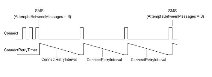
ConnectRetryInterval This field holds the value of the delay between failed connection attempts. The value is measured in seconds. After a reset, the module tries to connect up to 3 times. If connection fails, the module will wait ConnectRetryInterval time before another connection attempt. After AttemptsBetweenMessages attempts, an SMS may be sent to the phone number defined in the SMS register, reporting the actual error.
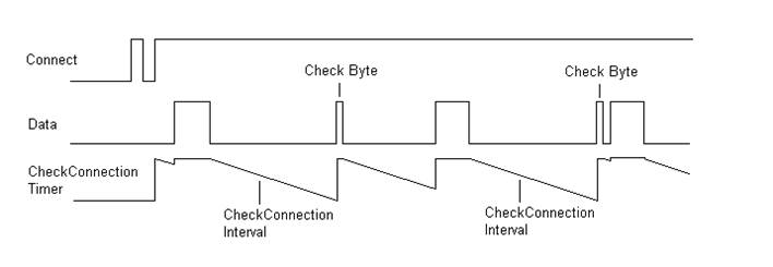
CheckConnectionInterval The GPRS module can send a small packet at a fixed time interval, to check if the TCP connection is present. The interval between these packets is inserted here. If the connection is not working, the module tries to establish it again. The smallest possible value is 900 seconds.
AttemptsBetweenMessages This field holds the number of failed connection attempts, before an SMS is sent. The module keeps sending an SMS every time the number of failed connection reaches AttemptsBetweenMessages.
RegNo 4: ErrorSMSPhoneNo
This field holds the phone number to which an SMS is sent if the automatic connection to the GPRS server fails. If no phone number is entered, no SMS is sent.
RegNo. 5: SIMFlagReg
FlagReg :
The FlagReg can be accessed as one Byte or as individual bits.
Bit 0: SIM write in progress The SIM write in progress flag indicates that the PD 664 is writing data to the SIM card. After a power-up or a reset of the module, the SIM write in progress flag is FALSE.
RegNo 6: ConfigSMSSecurity
FlagReg :
The FlagReg can be accessed as one Byte or as individual bits. The most significant bit determines the security level, e.g. if bit 2 is set TRUE, this overrides the settings in bit 0 and bit 1. If bit 1 is set, this overrides the setting of bit 0.
Bit 0: Serial number required for write If this bit is set, the serial number of the device must be included in the SMS when sending a ‘store’ message. If the correct serial number is included in a ‘store’ SMS, a response will be sent, if not the message will be ignored. A read message does not require the serial number, and will cause a response to be sent. Bit 1: Serial number required for read and writeIf this bit is set, the serial number of the device must be included in the SMS when sending either a ‘load’ or ‘store’ message. If the correct serial number is included in the SMS, a response will be sent, if not the message will be ignored. Bit 2: SMS configuration not permittedIf set, SMS configuration is not permitted. A message sent to the device will be ignored.
RegNo 7: SignalStrength
The fields in this register hold the received signal strength, represented as integers from 0 to 31. The numbers have the following meaning:
Actual This field holds the actual signal strength.
Min This field holds the lowest signal strength measured, since the PD 664 was powered up.
Max This field holds the highest signal strength measured, since the PD 664 was powered up.
SignalStrength will be updated 1-2 times a minute.
RegNo 8: Statistics
ReceivedPNETPackets This field holds the number of P-NET packets received from the TCP connection since the PD 664 was powered up, or since the counter was last reset.
SentPNETPackets This field holds the number of P-NET packets sent over the TCP connection since the PD 664 was powered up, or since the counter was last reset.
RegNo 9: Info
TCPStateThe TCPState variable can hold the following values: TCPState_Initialising (0): The PD 664 has been reset. TCPState_Idle (1): The PD 664 is not connected to the P-NET Gateway Service. TCPState_Connecting (2): The PD 664 is trying to connect to the P-NET Gateway Service. TCPState_Connected (3): The TCP connection is idle, sending or receiving packets.
IPAddress The IPAddress variable contains the IP assigned to the module by the service provider.
Datastorage The Datastorage variable can hold the following values: Datastorage_No_data (0): Datastorage_SIM (1): Datastorage_EEPROM (2) The state of Datastorage defines from which memorytype the module has loaded the configuration. The configuration is loaded during power-up or after a reset of the module. If the module is not able to find any configurations the state will remain as Datastorage_No_data.
RegNo 10: LastError
This Record holds information about the last registered error. After a power-up or a reset of the module, this record is cleared. The record is also cleared if Bit 10 (LastError) in RegNo 15: ChError.His is cleared manually.
* Please note that some of the errors do not generate an error text.
If the PD 664 GPRS Interface reports SIM PIN Code Error in RegNo 10 LastError, is it very likely that an incorrect PIN Code has been used. Please note that in the event of an incorrect PIN Code having been used several times, it may be necessary to unlock the SIM Card by inserting it into a mobile phone and entering the PUK Code.
RegNo. 11: GPRSFlagReg
FlagReg :
The FlagReg can be accessed as one Byte or as individual bits.
Bit 0: Offline If the Offline flag is set TRUE the TCP connection is disconnected immediately. After a power-up or a reset of the module, the Offline flag is FALSE.
Bit 1: Disable SIM PIN If the Disable SIM Pin is set to TRUE the PD 664 will try to disable the SIM PIN check using the PINCode entered in RegNo 0 Pincode. On completion of this task the flag will be set to FALSE by the software. If the Disable SIM PIN flag remains TRUE, please look in RegNo 10 LastError for a possible error.
Please note that if the SIM PIN is disabled, either done by the PD 664 as described, or if the SIM card was delivered with this setup, it cannot be enabled by the PD 664 interface. This must be carried out when the SIM card is inserted in a mobile phone.
RegNo. 12: SIMCardIDNo
This register holds the SIM Card ID number. If the string is empty, the ID has not yet been read from the SIM card, or no SIM card has been inserted into the module.
RegNo 14: GUID
Each channel type is identified by means of a unique GUID. The value of GUID for the GPRS channel is: PD/551299-01.
RegNo 15: ChError
There are two sets of error bits, actual and historical. The actual error bits reflect the current situation and will automatically follow any change. The historical error bits reflect the history and have the purpose of holding sporadic errors. The historical error bits are set together with the corresponding actual bits. They remain set after a read, so each individual bit must be cleared manually, via P-NET. Only the bits where the corresponding actual bit is false can be cleared. The “His data error” bit in the P-NET response is set if any historical bit is true. The “Act data error” bit in the P-NET response reflects the validity of the data in the response. An error in registers involved in calculating the result gives “Act data error”. See summary for how ChError.His can be cleared in particular M36 slave modules.
Bits 0 and 1 will cause Act error in the P-NET response on access to all variables.
Bit 0: Program_storage_fault is set if the self-test finds an error in the program memory.
Bit 1: RAM_storage_fault is set if the self-test finds an error in the data memory (RAM).
Bits 2 and 3 will cause His error in the P-NET response on access to all variables.
Bit 2: InternalReset is set if a reset is caused by a power failure, or if the power has been disconnected (only a His error).
Bit 3: ExternalReset is set if a reset is caused by writing 255 to Reset, via P‑NET (only a His error).
Bit 4 and 5 will cause Act error in the P-NET response on access to all variables.
Bit 4: ModuleError is set if a module error occurs.
Bit 5: SIM_not_inserted is set if no SIM card has been inserted into the cardholder.
Bit 6: GPRS_Network_Error is set to TRUE if the module’s internal self-test detects a network error and the network connection has been reinitialised.
Bit 8: EEPROM_Error_In_PINCode is set to TRUE if the module’s internal self-test finds an error in the PINCode variable stored in EEPROM. If the corresponding variable(s) is accessed, Act error in the P-NET response is set.
Bit 9: SIM_Error_In_GPRS_Config_Data is set to TRUE if the module’s internal self-test finds an error in GPRS config data stored on the SIM card. If the corresponding variable(s) is accessed, Act error in the P-NET response is set.
This error can occur if the power disappears, or the SIM card is removed when writing to SIM card. Consequently, a rewrite to the variable could perhaps solve the problem.
Bit 10: LastError is set when an error is reported in LastError Record. It is cleared when GPRS connection is operational.
Bit 11: SendErrorSMS_Failed is set if the sending of an ErrorSMS failed. It is cleared after a successful Error SMS transmission.
Bit 12: EEPROM_Error_In_ConfigSMSSecurity is set TRUE if the self-test finds an error in the data memory (EEPROM). An EEPROM fault is only set at power-up. If the corresponding variable(s) is accessed, Act error in the P-NET response is set.
Bit 13: EEPROM_Error_In_GPRS_Config_Data is set TRUE if the self-test finds an error in the data memory (EEPROM). An EEPROM fault is only set at power-up. If the corresponding variable(s) is accessed, Act error in the P-NET response is set. Configuration data is data in the registers: ConnectionProfile, TCPServer, TCPClient, ErrorSMSPhoneNo
This error can occur if the power disappears when writing to EEPROM. Consequently, a rewrite to the variable could perhaps solve the problem.
Bit 14: No_Valid_GPRS_Configuration is set TRUE if the module is not able to find a GPRS configuration within the SIM card or in EEPROM without sum check error.
|
||||||||||||||||||||||||||||||||||||||||||||||||||||||||||||||||||||||||||||||||||||||||||||||||||||||||||||||||||||||||||||||||||||||||||||||||||||||||||||||||||||||||||||||||||||||||||||||||||||||||||||||||||||||||||||||||||||||||||||||||||||||||||||||||||||||||||||||||||||||||||||||||||||||||||||||||||||||||||||||||||||||||||||||||||||||||||||||||||||||||||||||||||||||||||||||||||||||||||||||||||||||||||||||||||||||||||||||||||||||||||||||||||||||||||||||||||||||||||||||||||||||||||||||||||||||||||||||||||||||||||||||||||||||||||||||||||||||||||||||||||||||||||||||||||||||||||||||||||||||||||||||||||||||||||||||||||||||||||||||||||||||||||||||||||||||||||||||||||||||||||||||||||||||||||||||||||||||||||||||||||||||||||||||||||||||||||||||||||||||||||||||||||||||||||||||||||||||||||||||||||||||||||||||||||||||||||||||||||||||||||||||||||||||||||||||||||||||||||||||||||||||||||||||||||||||||||||||||||||||||||||||||||||||||||||||||||||||||||||||||||||||||||||||||||||||||||||||||||||||
|
|
||||||||||||||||||||||||||||||||||||||||||||||||||||||||||||||||||||||||||||||||||||||||||||||||||||||||||||||||||||||||||||||||||||||||||||||||||||||||||||||||||||||||||||||||||||||||||||||||||||||||||||||||||||||||||||||||||||||||||||||||||||||||||||||||||||||||||||||||||||||||||||||||||||||||||||||||||||||||||||||||||||||||||||||||||||||||||||||||||||||||||||||||||||||||||||||||||||||||||||||||||||||||||||||||||||||||||||||||||||||||||||||||||||||||||||||||||||||||||||||||||||||||||||||||||||||||||||||||||||||||||||||||||||||||||||||||||||||||||||||||||||||||||||||||||||||||||||||||||||||||||||||||||||||||||||||||||||||||||||||||||||||||||||||||||||||||||||||||||||||||||||||||||||||||||||||||||||||||||||||||||||||||||||||||||||||||||||||||||||||||||||||||||||||||||||||||||||||||||||||||||||||||||||||||||||||||||||||||||||||||||||||||||||||||||||||||||||||||||||||||||||||||||||||||||||||||||||||||||||||||||||||||||||||||||||||||||||||||||||||||||||||||||||||||||||||||||||||||||||||