Contents
1 General information.5
1.1 Introduction. 5
1.2 Features. 5
1.3 Construction. 6
1.4 Operating principles. 8
2 Function description. 9
2.1 Flow measurement9
2.1.1 Test mode. 9
2.2 Volume counter9
2.3 Automatic functions. 9
2.3.1 Batch Control9
2.3.2 Flow control10
2.3.3 Limit switch. 10
2.4 Temperature measurement10
2.5 Output1. 10
2.6 Output2. 10
2.7 Output3. 11
2.8 Input11
2.9 P-NET Interface. 11
2.10 PD 210 display unit11
3 Display. 12
3.1 Local display unit, PD 210. 12
3.2 Display registers. 12
3.2.1 Changing the register13
3.2.2 Configuration and
calibration using the PD 210. 13
3.2.3 Error readout13
3.2.4 Construction. 13
3.2.5 Assembly drawing for
PD 210. 13
3.3 Flowmeter-Display, PD 4000/340. 14
4 Installation. 15
4.1 Selecting the right meter size. 15
4.2 Installation of Transmitter16
5 Electrical
connections. 17
5.1 Power supply. 17
5.2 Output1. 17
5.3 Digtal output signals. 18
5.3.1 Output2. 18
5.3.2 Output3. 19
5.3.3 Output3, current
output19
5.4 Input signal21
5.5 Temperature signal, Pt-100. 21
5.6 Connecting the display unit, PD 210. 21
5.7 P-NET connections. 21
6 Variable description. 23
6.1 SoftWire Table. 23
6.1.1 Process variables. 26
6.1.2 Configuration and
calibration parameters. 29
6.2 Standard settings. 34
7 Applications. 35
7.1 Flow Control35
7.2 Batch control using the PD 210
display. 37
8 Fault finding. 39
8.1 Error detection. 39
8.2 Typical errors. 39
8.2.1 Flow Transmitter with
PD 210 display unit39
8.2.2 Flow Transmitter
without display unit40
9 List of spare parts. 41
9.1 Dimensions and capacities. 42
9.2 Material42
9.3 Connections. 42
10 Specifications. 43
10.1 Flow measurement43
10.2 Power Supply. 44
10.3 Liquid. 44
10.4 Measurement of temperature. 44
10.5 Environment44
10.6 Approvals. 44
11 Appendix. 45
11.1 3-phased output signals. 45
12 Appendix 2. 47
12.1 Memory types. 47
13 Appendix 3. 48
14 Index. 49
1 General
information.
The PD 340
flow transmitter is a precision meter for the volumetric measurement of
liquids, which are electrically conducting.
The transmitter can be used in applications where a hygienic design is
required. The rugged construction of the transmitter makes it suitable for
installations where solid particles are in the liquids.
The PD 340 transmitter is equipped with a microprocessor, which controls
and supervises all of its functions.
This manual
is applicable to Flow Transmitters marked with C or CE on the
electronic module.
·
Sanitary
design
·
Maintenance-free,
no moving parts
·
Automatic
zero point correction
·
Bi‑directional
flow
·
Volumetric
measurement in m3, litres, U.S. gallons etc.
·
Pulse
output to an electronic counter, 0‑1000 pulses per second
·
Pulse
output to an electromechanical counter, 0‑10 pulses per second
·
Current
output, 4‑20 mA (extended version)
·
Batch
control function
·
Limit
switch function
·
Flow
regulator function (PI controller)
·
Practically
no loss of pressure
·
A
display unit, PD 210, can be simply connected. The PD 210 unit can display accumulated
volume, Setpoint for Batch control or PI regulator, flow rate, temperature,
etc.
·
Count
stop/clear logic input function.
·
Temperature
measurement using an external temperature detector
·
Temperature
compensated flow measurement
·
Continuous
Selftest, which can be monitored through the P‑NET
·
P‑NET
Fieldbus Communication
·
EMC
approved (89/336/ECC)
·
Vibration
approved (IEC 68-2-6 Test Fc)
The PD 340 Flow Transmitter consists of three parts:
·
Meterhead
·
Electronic module
·
Terminal box
The electronic module and the terminal box are the same for all sizes of
transmitter.
The Meterhead consists of a stainless
metering pipe with clamp connections. Two magnet coils are mounted external to
the metering pipe. Two stainless electrodes are mounted inside the metering
pipe.
The measuring section is designed so that changes in flow profile do not affect meter accuracy. Hence the transmitter has a
wide range of flow rates within its linear accuracy. Changes from laminar to
turbulent flow do not affect the linear accuracy, and changing viscosity has
no affect on meter accuracy. The calibration of the meterhead is carried out during
manufacture using a computer controlled calibration facility.
The Electronic Module is micro‑processor
based and controls both the sequence of measurement and output signal transmission.
The use of the micro‑processor has enabled a compact design to be
achieved yet enabling many functions.
The electronic module is available in three versions, standard, extended
with current output and extended with 3-phase output. See appendix 1 for
further details.
The standard version has two pulse output signals and one logic input. The
transmitter can also be directly connected to a display unit.
In the extended version with current output, one of the pulse output signals
can be changed into an analog current output signal, 4‑20 mA.
In the extended version with 3-phase output, the normal separate pulse
output signals are transformed to a combined 3-phased output signal.
On both extended versions it is possible to connect the transmitter to a
P-NET Fieldbus (data communication network) for central data collection
or control.
The Terminal Box is completely separated
from the electronic module. Connections can therefore be changed without disruption
to the electronics. All terminals within the terminal box are clearly marked
with both number and function.
The box is also equipped with 3
cable glands, type PG 11.
The meterhead consists of a metering pipe and two magnetic coils. When a
current is applied to the coils a magnetic field is produced at right angles to
the metering pipe.
With a conductive liquid flowing through the metering pipe an electrical
voltage is induced and measured by two electrodes mounted in the metering pipe.
This voltage is proportional to the average velocity of flow and therefore to
the volume flowing.
The PD 340 Flow Transmitter utilizes a square measurement chamber. The
shape of the measurement chamber significantly reduces the influence of
viscosity, type of liquid, and flow profiles.
Practical tests with the PD 340
confirm that it is not necessary to recalibrate the meter when changing
product, for instance from water to milk. This would normally be necessary when
using mag meters with traditional round measuring chambers.
|
Figure 2: Operating principles
|
·
Ue = K
x B x V x D
·
Ue =
voltage across electrodes
·
K =
system constant
·
B =
magnetic field
·
V =
average velocity
·
D =
distance between electrodes
The micro‑processor in the
transmitter controls the current generator keeping the magnetic field constant.
The voltage across the electrodes is amplified and converted to a digital value
from which the micro‑processor calculates the liquid flow.
The Flow Transmitter holds a number of internal functions and
connections for external signals. The functions may be selected by keying in a
set of configuration parameters. Calibration parameters may also be set. The
data may be entered via a display/keyboard unit or via the P‑NET.
The Flow Transmitter may be scaled to operate in any volumetric units,
Litre, m3, Gallon etc. The flow rate may be selected to be displayed as volume
unit/hour or /minute.
2.1
Flow measurement
The flow rate may be filtered to stabilize the readout of an unstable
flow. Flow rates below 0.2 % may be ignored. This may be useful to avoid
totalizing the volume during long periods with no flow (see
configuration of function selector Code3).
The flow is measured in both directions. Flow following the arrow on the
meter head will be indicated as positive flow. Optionally the negative flow may
be ignored and set to zero (see configuration of
function selector Code3).
To compensate for the expansion of the liquid, the Flow Transmitter may
be configured to indicate a flow as if the liquid temperature was at 4 °C
(see also T.C. Flow).
2.1.1
Test mode
The Flow Transmitter may be set in test mode. During installation and
service, the test mode may be used to simulate that liquid is flowing in the
pipe system. All output signals, pulse signals as well as current signal will
act as if the liquid flow was present. This way, all internal functions,
external signals and cable connections may be checked (see
configuration of function selector Code2).
The Flow Transmitter utilizes two independent totalizers, Volume1 and
Volume2, which indicate the measured volume since they were cleared. Each
volume counter may independently be cleared or preset to a specific value (see further details in the Volume1 description).
A number of automatic functions are selectable in the Flow Transmitter.
Only one of the functions should be selected (see
configuration of function selector Code2 how to select each function).
The Flow Transmitter has a built-in batch control function, and can
therefore easily be used to control the dosing of a specified volume. The
requested volume is keyed into a setpoint register. A digital input on the Flow Transmitter may be used
to start the batch control. A digital output, Output2, opens the dosing valve
or starts a pump, when the setpoint volume is reached, the output is switched
off and the valve is closed or the pump stops. The Volume2 counter shows the
dosed volume.
See also the Batch control application example.
In systems where it is desirable to have a constant flow, the Flow
Transmitter with the built-in Flow Control function may be used directly to
control a valve or pump. The requested flow rate is keyed into a setpoint register and the internal PI
controller will control the valve or pump by means of the current output signal
(4-20 mA).
See the Flow control application example.
The Flow Transmitter has a built-in limit switch function. This function
may be used to indicate if a measuring value is below or above the value in the
setpoint register. As an example this may be used to indicate a high/low flow
rate. The indication may appear on a digital output, Output2, as ON or OFF (see configuration of function selector Code2 to select
this function for Output2).
The Flow Transmitter can measure temperature by connecting an external
temperature detector, type Pt‑100. The temperature may be read in a
register as °C or °F (see configuration of function selector Code3).
This is necessary for temperature compensated flow measurement.
Output1 is a power supply output, which can be used to supply an external counter or
relay circuit (see further details in chapter 5.2).
Output2 can be selected for one of several functions (see configuration of function selector Code2):
·
Pulse signal, 0‑10 Hz. The
signal may be taken to a counter, electronic or electromechanical, for
indication of the total volume, e.g. in litres (see chapter 5.3.1Output2).
·
Sign
for Output3. The signal indicates the flow direction. The output is switched
OFF, when the flow is positive. By means of an UP/DOWN‑counter
this signal may be used for the totalizing of the volume flowing with a
sign.
·
Control
signal from the Batch control function.
·
Control
signal from the Limit function.
·
Error
free measurement signal. The output signal is ON if no error is present.
·
The
output may be controlled directly via P-NET.
Further details for connecting Output2 is found in chapter 5.3.1Output2.
Output3 may be used as a digital
signal output or as an analogue 4-20 mA current output (extended version PD 366 only). When used as a digital
signal, it may be used as a fast pulse signal (0 - 1000 Hz) for external counter circuits (see scaling
example in chapter 6)
or it may be controlled directly via P-NET. Further details for connecting
Output3 are found in chapter 0
Output3.
The transmitter has a logic input, Input1, which can be selected for
one of several functions (see configuration of function
selector Code3):
·
Stop counters. The signal may come
from an air detector, and is then used to make the transmitter stop counting,
when there is air in the liquid.
·
Clear Volume2 counter. The input can
be used in batch control, to start the Batch
function and clear the batch volume counter.
·
Manual/Automatic
mode for PI controller. The input can be used
to set the operation mode for the PI controller.
Further details for connecting Input1 are found in chapter 5.4Input signal.
The extended versions of the Flow Transmitter utilize a P-NET fieldbus
communication interface. This enables the Flow Transmitter to be connected
directly to P-NET. P-NET is a fieldbus network designed for process control
and data-collection. P-NET is a RS-485 Serial interface used for communicating
with P‑NET interface modules with a transmission speed of 76,800 baud
(see chapter 5.7 for further details).
Through the P-NET it is possible to display and change all the internal
data within the Flow Transmitter (see a complete list
in the Variable Description).
The PD 4000 Flowmeter-Display utilizes the P‑NET interface for data exchange
between the Flowmeter-Display and the connected Flow Transmitters. It is
possible to change data and to select various functions in the Flow
Transmitter. The memory in the Flowmeter-Display is equipped with a battery
backup, which will hold the measured data during a power failure.
The P-NET interface may also be used for data collection, eg. from a PC. The PC may be equipped with a PC P-NET interface board, which makes
it possible to directly access any variable in the Flow Transmitter and other
connected P-NET modules from a PC-program.
The PD 210 is a local display unit, which is connected directly to the Flow Transmitter. From
this unit it is possible to display the flow rate, volume counters,
temperature, setpoint etc. Furthermore the PD 210 display unit may be used to
change setpoint values and to perform a complete configuration of the Flow Transmitter.
The display unit is connected to the Flow Transmitter with a two-wire
cable, up to a length of 100m. The display unit is supplied with power via this
cable. It also carries the exchange of data between the Flow Transmitter and
the display unit (see description in chapter 3).
Various options are available for displaying information from the PD 340
Flow Transmitter. The Flow Transmitter may be controlled and supervised via the
P-NET interface (requires one of the extended versions), all data may then be accessed.
Another solution is to connect a local display unit to the Flow Transmitter, PD 210. Then only the main data is accessible.
The display unit PD 210 can be connected directly to the transmitter. With this unit you
can perform different functions.
·
Display
of data from the transmitter, e.g. flow or volume.
·
Changing
of data in the transmitter, e.g. contents of volume register or SET‑point
register.
·
Configuration
and calibration, e.g. setting of the size of the meterhead or the function of
the output signals.
·
Readout
and reset of an internal error code.
The display unit is connected to the
Flow Transmitter with a two-wire cable, up to a length of 100m. The display
unit is supplied with power via this cable. It also carries the exchange of
data between the Flow Transmitter and the display unit.
|
The contents of 8 different registers in the transmitter can be displayed
on the unit. A touch on one of the 8 buttons under the display selects whichever
register you want to read. The display indication is automatically updated
about once per sec. Additional details may be found in chapter 6.1.1.
|
|
|
|
Reg. No.
|
Name
|
Function
|
SWNo
|
|
1
2
3
4
5
6
7
8
|
FLOW
T.C.FLOW
TEMP
“blank”
VOL.1
VOL.2
SETP.
”blank”
|
Liquid flow, e.g. in m3/h
Temperature compensated flow
Temperature in °C
Available register
Volume, result of totalization,
e.g. in m3
Volume for comparing with SET‑point,
e.g. in m3
SET‑point, e.g. in m3
Instant Flow
|
$11
$12
$13
$14
$15
$16
$17
$18
|
|
|
|
|
|
|
If a change in the contents of a register is required, the register must
first be displayed. Then the desired contents are entered, followed by a touch
on the = button. This gives a blank display for approx. 1 sec., and then
the new contents are displayed in the normal way.
The Flow Transmitter contains 8 configuration registers. See also chapter 6.1.2 for a detailed explanation and purpose for these
registers (the registers are located on SoftWire number 20 to 27). If you want
to display the contents of a configuration register, touch the E button,
which will turn the display blank. Then touch a numeral key between 1
and 8 to choose a configuration register. The number of the
configuration register appears in the first digit of the display, and the
contents of the register in the rest of the display. Changing the contents of a
register are performed by keying in the new contents, and touch the =
button.
The user is informed by an "A" for ALARM appearing in the
first digit of the display. By pressing the "TEST" button the display will show an error code of two digits, indicating the type of error. The test system
ensures that the alarm will not be cancelled before the error code has been
displayed by pressing the "TEST" button, even though the error may
have disappeared. By pressing the "TEST" button once again, the display
will show "0" if the Flow Transmitter is error free now. The error
code on the display is only updated by re‑pressing the
"TEST" button. A complete list of error codes
are given in chapter 6.
The display unit consists of a LCD‑display, a keyboard and
electronics for exchange of data with the transmitter, and control of the
display and the keyboard.
The unit is built into a box of NORYL PPO, sealed to IP 65. The
dimensions of the box are LxHxD = 144 x 72 x 8 mm. (Standard dimensions for
cabinet instruments).
The electronics are based on a micro‑processor, which controls the
LCD‑display, scans the keyboard and controls the communication with the
transmitter.
|
NOTE: Please observe that the M3
mounting screw holes are only 4 mm. deep.
Do NOT screw down beyond this length. This may damage the display
unit.
|
|
The Flowmeter-Display is based on a PD 4000 P-NET Controller and is designed to display data from PD 340
Flow Transmitters. Furthermore it is possible to change data and to select
various functions in the Flow Transmitters.
The displayed data may be e.g.
flow or volume, or a setpoint or filterconstant may be selected for
modification.
Up to three Flow Transmitters may be selected and supervised
simultaneously on the Flowmeter-Display. The Flowmeter-Display is connected to
the Flow Transmitters in a P-NET Fieldbus system.
A standard configuration for a PD 340 Flow Transmitter is stored in the
Flowmeter-Display and may be transferred automatically via P-NET to a new Flow
Transmitter in the system. The standard configuration may be adjusted to match
a specific customer configuration.
The actual configuration for each of the selected Flow Transmitters may
be listed in clear text on the display.
Please refer to the Flowmeter-Display manual (502 071) for additional
information.
The Flow Transmitter has a very large measuring
range. The optimal flow measurement is obtained when the flow rate is close to,
but below the maximum flow rate for the Flow Transmitter. Flow rates greater
than the maximum specified flow rate + 10 % are not measured and
therefore not registered. This means that the flow rate must never exceed
the maximum specified value.
Practical examples from different installations indicate that the flow rate
varies. Therefore it is recommended that the calculated maximum flow rate
should not exceed 90 % of the specified maximum flow rate for the
selected Flow Transmitter. Exceptions may be made if the flow rate is well
known and very stable.
If the operational flow rate for a Flow Transmitter is below 30 % of the
maximum flow rate for the Flow Transmitter, it is recommended to select a
smaller dimension, if existing.
Flow measurement down to 5 % of maximum flow rate for the Flow Transmitter, or even
lower is also possible, but with a reduced accuracy (+/- 1 %).
The size of the meterhead should be selected according to the maximum
flow rate. This maximum flow rate must be the absolute maximum flow rate during
operation, cleaning, startup etc. The smallest possible transmitter is then
chosen for that maximum flow rate. This will ensure optimum measurement
accuracy. If the metering section is smaller than the pipework in the
installation, the connecting pieces should be tapered.
A Flow Transmitter should not be installed in a pipe construction where
the pipes are smaller than the pipes in the connections.
If two products are mixed before measuring, the mixed product must be a
homogenous liquid before entering the Flow Transmitter to ensure maximum
accuracy.
The Flow Transmitter is available in 5 different sizes as shown in the
table below:
|
Max. flow rate:
|
|
|
|
|
|
C 25
|
C 38
|
C 51
|
C 63
|
C 76
|
|
8 m3/h
|
20 m3/h
|
40 m3/h
|
80 m3/h
|
120 m3/h
|
NOTE:The
max. flow rate for the Flow Transmitter must NEVER be exceeded. Otherwise the
meterhead may be damaged.
The transmitter should be installed within the pipe work system such
that the metering pipe is always filled with liquid, as the transmitter can
register flow, even if the meter is empty.
As the transmitter sees air in the liquid as a volume, the volume of air in the liquid must be
reduced to a minimum, and the transmitter should be located in the pipe work system,
at the point of maximum pressure. Here the volume of the air is at a minimum
and the influence of air on the measurement will also be at a minimum.
If heavy vibrations occur in the pipe work e.g. caused by resonance from pumps,
or a pulsating pressure in connection with e.g. a homogenizer or a positive
displacement pump, a vibration damping is required, or the transmitter must be
mounted somewhere else with less variation of pressure.
If the liquid contains air, an air eliminator should be mounted before
the Flow Transmitter.
The transmitter can be mounted
both horizontally and vertically. No air must be trapped in the meter head.
The positive flow direction is indicated by an arrow on the meterhead.
To create the best conditions for precise metering, a straight pipe
run of least three times the pipe work diameter should be mounted upstream and
downstream of the transmitter.
When selecting the location of the transmitter it must be ensured that
the ambient temperature is within the specified limits. Finally, the
transmitter should be installed such that the electronic module and the
terminal box can be fitted and dismantled in situ.
NOTE:The
clamp connections must be loosened completely before the transmitter is
rotated. Otherwise the meterhead may be fatally damaged.
Precautions must be taken to ensure that neither the electronic module,
the meterhead nor the terminal box are exposed to moisture, when the
transmitter is dismantled. To prevent moisture, the cables must be mounted
correctly in the glands. The electronic module and the terminal box must be
carefully mounted with all screws tightened.
The Flow Transmitter supply should always be connected, as heat
developed in the electronic module prevents condensation, which could damage
the transmitter. As soon as possible after mounting, the transmitter should
therefore be powered up.
The
figure below shows the terminal board with all the electrical connections for
the Flow Transmitter. The program enable switch, SW1 located in the upper left corner, must
be in the ON position to configure and calibrate the Flow Transmitter. After
configuration and calibration the switch must be set in the OFF position.
|
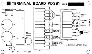
Figure 3:
Electrical connections in Terminal Board
|
The power supply for the Flow Transmitter may be 24 V DC or 24 V AC.
If the conductivity for the liquid is below the specified 5 μs/cm, it
might still be possible to measure the flow. To do this, the Flow Transmitter
must be connected to a separate DC power supply where the -24 V DC terminal
must be connected to the piping system.
This will increase the sensitivity and flow measuring may be possible.
|
Output1 on the terminal board is a voltage supply, which can be used to
supply an external counter circuit, relays or current devices (4-20 mA).
The voltage at the output can
vary from 20 to 40 V DC, depending on the power supply voltage (Supply
voltage - 2 V as minimum).
|
Figure 4: Power supply output
electrical
|
The voltage supply is connected
directly to a bridge circuit, which rectifies the power supply voltage to the
transmitter. The output is protected with a zener diode and a current‑limiting
resistor in the same way as the pulse outputs. Furthermore, the output is
isolated from the internal electronics by a transformer. The output is not
isolated from the power source supplying the transmitter.
The Flow Transmitter has two digital output signals, Output2 and
Output3. Voltage supplies are required for output signals.
The outputs are isolated from the other part of the electronics by
optocouplers. Furthermore, the outputs are protected against overload by a
zener diode and a current‑limiting resistance, RPTC. RPTC
is about 25 Ohm at normal load (max. 100 mA). At overload, the RPTC
will rise rapidly thus limiting the current to about 16 mA.
|
If an output has been overloaded, the current must be completely switched off for some
seconds, by switching off the power supply to the Flow Transmitter, before
the output can be normally loaded again.
A voltage drop of up to 1.0 V may occur when the output is switched
ON. This should be noted when connecting to low voltage external equipment.
|
|
|
In case of wrong polarization of the connection, the signal acts as a
constant ON signal.
|
The pulse output signal from
Output2 has a pulse width of 40 ms. The frequency is continuously variable from 0‑10 Hz.

Pulse signal Output2
Example of electrical connection of electro‑mechanical counters.
|
Counter specification:
Supply voltage: 20‑40
V DC
Power consumption: Max.
2.5 W
Counting frequency: Min.
10 Hz
ON‑time: Typ.
40 ms
OFF‑time: Min.
60 ms
|
|
The
standard version of the Flow Transmitter can generate a pulse output signal at
Output3. A voltage supply is required for this pulse output signal.
The current output extension
board, PD 366, for the Flow Transmitter can generate two different output
signals at Output3, pulse output signal or analog current
output signal. Voltage supplies are required for both types of signals.
The pulse output signal from Output3 is symmetrical (50 - 50 % duty
cycle), and the frequency is continuously variable from 0‑1000 Hz.
Electronic counters and PLC's are normally connected to the pulse
output, Output3.
The pulse output in the transmitter consists of a voltage free
electronic switch contact. Therefore, it is necessary to equip the count pulse
input on the counter/PLC with a pull‑up resistance, if the counter/PLC
has no internal pull‑up.
|
The pull‑up resistance R1 should be chosen so that the current
I is approx. 5 mA when the contact in the Flow Transmitter is switched on.
|
|
The current output signal is in the range from 4 - 20 mA. The current output
may be taken to a regulator for controlling the liquid flow.
|
The current output from Output3 is working as a variable resistance.
Therefore it requires an external supply voltage, which can provide min. 12 V
at the terminals 17 and 18 in the Flow Transmitter + the voltage drop across
the load and cable. The necessary supply voltage must be calculated for max.
current, 20 mA.
|
|
|
The current output is isolated from the other part of the electronics
and protected against overload in the same way as the pulse outputs. However,
the current‑limiting resistance RPTC is designed so that overload protection comes into force at about 35 mA.
|
|
|
Supplied by internal voltage
supply (Output1).
|
|
|
|
|
|
|
|
Supplied by an external power supply.
|
|
|
|
|
|
The input signal is galvanically isolated. To activate the input, a
voltage of minimum 18 V must be connected to the terminals with the right
polarization. This voltage may be supplied from either the internal voltage
supply or an external power supply.
|
|
A standard Pt-100 temperature sensor may be connected to the Flow Transmitter. The temperature
sensor must be connected with a 4-wire cable all the way from the sensor to the
terminal box. This must be done to avoid errors influenced by the cable,
junctions and connections.
NOTE:If
a temperature sensor is not used, the terminals 9‑10‑11‑12 must
be connected together to avoid errors in the flow measurement.
The display unit is connected to the Flow
Transmitter with a two wire twisted cable, up to a length of 100m. The display
unit is supplied with power via this cable. It also carries the exchange of
data between the Flow Transmitter and the display unit.
The communication speed between the Flow Transmitter and the PD 210
display unit is 300 bit/sec, resulting in a new data readout approx. each second.
To improve the electrical noise immunity at long distance cables, a
shielded cable is recommended. The shield must then be connected to terminal 8
at the terminal box and not connected at the display unit.
The P-NET is a multi drop bus, which is connected in a physical ring. Up to
125 units can be connected to the bus, where a unit may be a PD 340 Flow
Transmitter, a Flowmeter Display or another P-NET interface module. The P-NET
interface is galvanically isolated. The bus cable is a twisted pair with
shield, and the shield is used as a potential equalizer between the
driver/receiver circuits in the nodes connected to the bus.
A P-NET unit is connected to the bus by means of 3 terminal-connections,
the A terminal, the B terminal and the S terminal.
The connection from one unit to the next unit is performed by connecting
A to A, B to B and S to S. The S terminal must not be connected to
ground. If the length of the cable is more than 100 m, the bus cable will have to be connected from field device to field device,
forming a physical ring.
Electrical specification for P-NET:
|
Bus structure:
|
A physical ring without termination.
|
|
Medium:
|
Shielded twisted pair cable with minimum .22 mm² area conductors and
characteristic impedance of 100-120 ohm. For example TWINAX IBM part No.
7362211 with 105+/-5 ohm, 51 pF/m.
|
|
Bus length:
|
Max 1200 m (EIA RS 485).
|
PD 340 Flow Transmitter holds a number variables and functions, which all
may be accessed via P-NET and some via the PD 210 display unit.
The variables in the PD 340 Flow Transmitter are located on logical addresses called SoftWire
numbers. These variables include the size of the meterhead, setpoint for the PI
regulator, function of output signals etc. A survey of these variables and
related SoftWire numbers are given in the following SoftWire table. The memory
type is explained in Appendix 2.
At delivery, the transmitter is programmed for the functions specified
on the order.
|
SWNo
(hex)
|
Identifier
|
Memory
type
|
Read
out
|
Type
|
SI
Unit
|
|
0
1
2
3
4
5
6
7
..
11
12
13
14
15
16
17
18
..
20
21
22
23
24
25
26
27
|
SerialNo
DeviceType
PrgVers
Error3
Output2
Output3
Input1
BatchStart
Flow
TcFlow
Temperature
Available
Volume1
Volume2
SetPoint
InstantFlow
MeterSize E1
Ti E2
PICode E3
MeterNumber E4
Scale E5
Code1 E6
Code2 E7
Code3 E8
|
Special function
PROM Read Only
PROM Read Only
RAM Read Write
RAM Read Write
RAM Read Write
RAM Read Only
RAM Read Write
RAM RPW
RAM Read Only
RAM Read Only
RAM Init EEPROM
RAM Read Write
RAM Read Write
RAM Init EEPROM
RAM Read Only
EEPROM RPW
RAM Init EEPROM
RAM Init EEPROM
PROM Read Only
RAM Init EEPROM
EEPROM RPW
EEPROM RPW
EEPROM RPW
|
Hex
Decimal
Decimal
Hex
Hex
Hex
Hex
Hex
Decimal
Decimal
Decimal
Decimal
Decimal
Decimal
Decimal
Decimal
Decimal
Decimal
Hex
Hex
Decimal
Hex
Hex
Hex
|
LongInteger
Integer
Integer
Byte
Byte
Byte
Byte
Byte
Real
Real
Real
Real
Real
Real
Real
Real
Real
Real
LongInteger
LongInteger
Real
LongInteger
LongInteger
LongInteger
|
*1
*1
*2
*3
*3
*3
*3
*3
s
*4
|
NOTES:
1.
Flow may be read out as 'unit/min' or 'unit/hour'
2.
The
unit for Temperature may be °C or °F
3.
The
unit for Flow depends on the calibration factor inserted in MeterSize.
4.
If
Output3 is regulator, the SI unit for Scale must be the same as for Flow.
P-NET SWNo 0:
SerialNo
PD
210 display: not accessible
This
register contains a production number, which is set by PROCES-DATA, and
it cannot be changed. The serial number is printed on the side of the Flow
Transmitter.
The
serial number is used for service purposes and as a 'key' to set the P-NET
number for the Flow Transmitter. When setting the P-NET number, the least significant
byte in the serial number holds the P-NET number, thus the serial number is
contained in the 3 most significant bytes (6 digits).
Setting
the P-NET number via the serial number is done by writing into the serial number
(possibly with receiver number = $7E (hex)).
The last
data byte must hold the P-NET number for the Flow Transmitter. The first 3
bytes must contain the same serial number, which already was in the 3
most significant bytes. If the two serial numbers are not identical, the P-NET
number will not be set.
Read out
of the P-NET number via the serial number is done by reading the serial number
and then masking for the least significant byte (possibly with receiver number
= $7F (hex)).
NOTE: When
reading the P-NET number / serial number with receiver number = $7F, all
modules on the P-NET will answer, thus only one module must be connected to the
P-NET. When setting the P-NET number via the serial number with receiver number
= $7E, all modules on the P-NET will receive the message, but will give no
reply (as in a normal transmission), hence a transmission error is generated.
P-NET SWNo. 1: DeviceType PD
210 display: not accessible
This
register holds information on the type of device, and may only be read out via
P‑NET. The device type for the Flow Transmitter is 340.
P-NET SWNo. 2: PrgVers PD
210 display: not accessible
This
register holds information on the program version, and may only be read out via
P-NET. The current program version is 8701.
P-NET SWNo. 3: Error3 PD
210 display key: TEST
The flow
transmitter is equipped with a comprehensive test system, which
is able to disclose faults, arising from improper use of the transmitter or
faults arising from the transmitter during use. When the test system registers
a fault, an error code is
generated and saved in this register. If more than one error occurs at the same
time, only the highest error code will be saved. The error code will be saved
until it has been read out. By reading out the error code twice, one can see if
the error has disappeared again. The error codes F0 through F4 can only be read
out via P-NET. By writing $FF (hex) in Error3, the Flow
Transmitter will perform a Reset and error code
$F2 will be generated.
The
display unit PD 210 will show the text "P.FAIL" after resetting the
transmitter what ever caused the reset.
|
ERROR CODE FAULT TYPE
|
|
F4 RESET due to
internal error
F3 RESET due to
internal error
F2 RESET due to $FF in
error code via P-NET
F1 RESET due to
internal error
F0 RESET due to power
cut
83 Error in program
storage (PROM)
82 Error in program
execution - watchdog
81 Error in data
storage (RAM)
80 Error in program
execution
76 Error in
EEPROM-storage
75 Error in
RAM-storage or EEPROM-storage
64 Improper connection
of temperature detector
63 Improper connection
of temperature detector
62 Temperature
detector disconnected
54 Magnetic coil in
meter head disconnected
(may also occur
from empty metering pipe in C marked meters)
52 Magnetic coil in
meter head short-circuited
(may also occur
from empty metering pipe in C marked meters)
44 Shunt in meter head
defective
43 Shunt in meter head
defective
42 Shunt in meter head
defective
24 Temperature
>> max
23 Temperature >
130 °C / 266
°F
08 Overrun, volume
counter 2
07 Overrun, volume
counter 1
05 Input active
04 Flow >> max /
metering pipe empty
03 Flow > max
02 Overflow, Output2
01 Overflow, Output3
|
|
|
P-NET
SWNo. 4: Output2 PD
210 display: not accessible
This register may be used to control Output2 and holds
information about the current state for the output.
If an
automatic function is selected for Output2, the output cannot be controlled via
this register, but the automatic function will control the state of Output2.
Output2
= 00=> Output
OFF
Output2
= 01=> Output
ON
P-NET SWNo. 5: Output3 PD
210 display: not accessible
This
register may be used to control Output3 and holds information about the current
state for the output when it is used as a simple digital output.
If an
automatic function is selected for Output3, the output cannot be controlled via
this register, but the automatic function will control the state of Output3. In
this case the state for Output3 will change rapidly, depending on the output
pulse frequency or current output value and there is not much point in reading
the state.
Output3
= 00=> Output
OFF
Output3
= 01=> Output
ON
P-NET SWNo. 6: Input1 PD
210 display: not accessible
This register
holds information about the current state for Input1. Input1 cannot be controlled.
Input1
OFF => Input1 = 00
Input1
ON => Input1 = 01
P-NET SWNo. 7: BatchStart PD
210 display: not accessible
When the
Output2 function is set to batch control,
batching is started either by activating Input1 or by inserting 01 in this
register. The register is reset immediately, the volume counter Volume2 is
cleared, Output2 will go ON and dosing starts.
P-NET SWNo. 11: Flow PD
210 display key: FLOW
This
register shows the current Flow rate for the liquid in the Flow Transmitter.
The Flow rate is an averaged value, where the time constant for the digital
filter and the time unit may be selected in the Code3 register. The time
constant for the filter can be chosen in the interval from approx. 0.15 sec. to
approx. 10 sec. Reverse flow
(relative to the arrow on the meter head) can be set to 0, as well as Flow
rates smaller than 0.2% of max. flow can be set to 0 (selected in Code3).
P-NET SWNo. 12: TCFlow PD
210 display key: T.C.FLOW
In
addition to the normal flow measurement, the Flow Transmitter also measures a
temperature, which may be used to calculate a temperature
compensated flow.
The
calculation of the temperature compensated flow is performed to compensate for
the expansion of the liquid as a function of the liquid temperature.
The Flow
Transmitter automatically calculates the temperature compensated flow by multiplying
the flow rate by a temperature dependant correction factor, K.
The
temperature compensated flow, TCFlow, may be read directly in this register.
The
relation between temperature and K is stored in the Flow Transmitter and is
shown below.
Implementing
an automatic calculation of TCFlow in the entire temperature range requires a Pt-100 temperature sensor
to be connected at the terminals 9, 10, 11 and 12.
Temperature
compensation may be implemented for liquids at fixed temperature without using
a Pt-100 temperature sensor. This is showed in the following example:
The
liquid is at a fixed temperature of 75 °C during production, no Pt-100 sensor is connected,
but temperature compensated flow is wanted for the volume counters.
The value
for the correction factor K is read from the above diagram, 0.975. This value
is now multiplied with the value from SWNo. 20 (PD 210: E1), Metersize
and stored back in Metersize. The Code2 register, digit 4 must be 1 to
select Flow as data for volume counters.
NOTE:Using this kind of temperature compensation
will only give the correct result when the liquid is at the fixed temperature.
P-NET SWNo. 13:
Temperature PD
210 display key: TEMP
This
register shows the temperature,
calculated relative to the Pt-100 detector connected to the Flow Transmitter.
If the four terminals for the temperature detector are short-circuited, the
calculated temperature will be approx. -245 °C, equal to -409 °F. The calculation unit for temperature is selected in
the Code3 register.
P-NET SWNo. 14: Available PD
210 display key: "blank"
The
Available register has several functions
depending on the selected options for Output3 and Batch control / Limit switch:
·
If the
Output3 function is set to current
output with PI-regulator, the Available
register contains the output value from the
regulator. The output value will be in the range from 0 to 100%, corresponding
to 4-20mA or 20-4mA depending on the selection in the PICode register. If the PI-regulator
is in Manual operation, then a value may
be written into the Available register, giving the output value for the current output.
·
The
Available register may be used as Data input for
Batch control / Limit switch.
·
If
none of the above options are selected, this register may be used as a free
register.
P-NET SWNo. 15: Volume1 PD
210 display key: VOL.1
This register shows one of the two internal volume counters in
the transmitter. The counter increments when the flow is positive and
decrements when the flow is negative.
The
read-out resolution (number of digits after the decimal point) on the PD 210 display unit for the
counter is chosen in the Code1 register. This read-out resolution also
determines the overflow value for
the counter. The counter value uses a total of 6 significant digits including
the digits after the decimal point.
When the
counter has reached it's maximum, error code 07 is generated, and the counter
starts from 0 again. The maximum value for the counter is reached when all 6
significant digits show the value 9. The corresponding volume depends on
the counter resolution.
If the resolution is 3 digits after the decimal point and the meter size is
inserted in m3, maximum will be 999.999 m3 - even
if there is no PD 210 display unit connected to the transmitter.
P-NET SWNo. 16: Volume2 PD
210 display key: VOL.2
The
Volume2 counter is similar to the Volume1 counter, though error code 08 is
generated at overflow. Furthermore it is possible to clear Volume2 by means of
Input1 or Batchstart.
P-NET SWNo. 17: Setpoint PD
210 display key: SETP.
The
Setpoint register has several functions depending on the selected options for
the PI-regulator and Batch control / Limit switch:
·
If the
Output3 function is regulator, the setpoint for the
regulator is inserted here. The setpoint is inserted in the same unit as the
amount to be regulated - e.g. m3/h.
·
If the
Output2 function is Batch control, the setpoint for the
batching is inserted here. After batch start (via Input1 or BatchStart) Output2
will be ON until the volume counter has reached the Setpoint. This function works for
positive values only.
·
If the
Output2 function is Limit switch, the limit is inserted
in this register. If data for the limit switch is below the limit, Output2 will
be OFF. If data is above the limit, Output2 will be ON.
As
Setpoint may be used for Output2 as well as Output3, it is not possible
though to choose regulator function for Output3 and batch control or
limit switch function for Output2 at the same time.
P-NET SWNo. 18: InstantFlow PD
210 display key: "blank"
This
register shows the flow directly as it is measured in the transmitter.
·
The
read out is without smoothing through the digital filter
·
Reverse flow is shown
·
Flowrates
lower than 0.2% of maximum flow is shown
·
The
actual flow is shown - even if the transmitter is in TEST-mode.
P-NET SWNo. 20: MeterSize PD
210 display address: E1, Size of Meter
The meter
size, stated on the meter head, is inserted in this register. On the meter head
the meter size is stated in m3/h. If another volumetric unit is
desired, the value in MeterSize is converted to this unit and stored as the calibration factor.
This value must always be stated in volume units per hour - even if the
de sired Flow read out is volume per minute.
Example: On the meterhead the meter size is stated as
80 m3/h. The desired volume unit is litres. Insert 80000 in MeterSize.
P-NET SWNo. 21: Ti PD
210 display address: E2, Integration time Ti
Ti is the
integration time constant for the PI-regulator, which
is the time it takes for the I‑component of
the regulator to give the same change in the output signal as that made by the
P-component, following a permanent change of the input signal.
See also
the application example Flow control.
Please
consult the scientific literature in this field for further information on how
to set the regulator parameters.
P-NET SWNo. 22: PICode PD 210 display
address: E3, PI-regulator function
The content of this register defines the function of the PI-regulator and the
current output (where in determines the calculation of the input signal
and out determines control direction for the current output). The
register also holds an operation mode selector (Manual/Auto).
The data
type for PICode is a LongInteger, which may be considered as 8 digits in hexadecimal
readout. The first 6 digits represent and select an optional function. Digit 7
and 8 are not used and should be set to 0. The information must be interpreted
as shown below (only digits 1 to 6 are applicable to the PD 210 display unit):
Va l.
|
Dig. 1
|
Dig. 2
|
Dig. 3
|
Dig. 4
|
Dig. 5
|
Dig. 6
|
Dig. 7
|
Dig. 8
|
|
|
|
|
|
Regulator Function
|
Regulator operation mode
|
|
|
|
0
|
0
|
0
|
0
|
0
|
in=setpoint-data out 0-100%:4-20mA
|
Auto
|
0
|
0
|
|
1
|
|
|
|
|
in=data-setpoint out 0-100%:4-20mA
|
Manual
|
|
|
|
2
|
|
|
|
|
in=setpoint-data out 0-100%:20-4mA
|
Input ON => manual operation
|
|
|
|
3
|
|
|
|
|
in=data-setpoint out 0-100%:20-4mA
|
|
|
|
P-NET SWNo. 23: MeterNumber PD
210 display address: E4, Meternumber
From this
register the Flow Transmitter's serial number may be
retrieved. This number is set by PROCES-DATA and is for service purposes
only. The serial number is printed on the side of the Flow Transmitter.
P-NET SWNo. 24: Scale PD
210 display address: E5, Output3 scaling
This register is used for the scaling of Output3 when
it is used as pulse output or current output.
If the Output3 function is pulse output,
0 to 1000 Hz, the number of volume units per pulse is stated in Scale.
Example:
The meter size (MeterSize is read in E1 at the PD 210 display unit) is 20000
litres per hour. The requirement is 0.01 litres per pulse on Output3 (equal to
100 pulses per litre). The figure 0.01 is then inserted in Scale
(E5 on PD 210).
In this
example a flow of 20000 litres per hour will give a Output3 frequency of

1
|
NOTE: Be sure
that the frequency on the output does not exceed 1000 Hz.
If the Output3 function is current output,
4 - 20 mA, Scale will indicate
the full-scale value of the data for the current output.
Example: Full scale (20 mA) is desired on the
current output at 15000 litres per hour. The number 15000 is inserted in Scale.
4 mA always equals a measuring result of 0.
If the
function of Output3 is PI-regulator, Scale
will indicate the proportional band of the regulator. The proportional band
for a regulator is the change required in the input signal to give a change
from 0 to 100% in the output signal (without I). The proportional band is
defined in the same unit, as the input signal to the regulator - e.g. m3/h.
See also
the application example, Flow control.
Please
consult the scientific literature in this field for further information on how
to set the regulator parameters.
P-NET SWNo. 25: Code1 PD
210 display address: E6, Display resolution
Using the
display unit, various measuring results may be read out from the Flow Transmitter.
For these values, Code1 determines how many digits to appear after
the decimal point. The resolution may be in the range from 0 to 6.
The data
type for Code1 is a LongInteger, which may be considered as 8
digits in hexadecimal readout. The first 6 digits represent and selects the
resolution for one register. Digit 7 and 8 are not used and should be set to 0.
The information must be interpreted as shown below (only digits 1 to 6 are
applicable to the PD 210 display unit):
|
Digit 1
|
Digit 2
|
Digit 3
|
Digit 4
|
Digit 5
|
Digit 6
|
7
|
8
|
|
Flow
|
TCFlow
|
Volume1
|
Volume2
|
Setpoint
|
Instantflow
|
|
|
For digit
3, Volume1 and digit 4, Volume2, the resolution determines also the maximum
value for the counters, i.e. the overflow value. See also the description for Volume1.
Example: The size of the transmitter is 80 m3/h. Flow
is requested on the display with a resolution of 0.01 m3/h. Set digit 1 in
Code1 equal to 2 (2 digits after the decimal
point).
When the Output2 function is
pulse output, 0 - 10 Hz, the resolution on Volume1 indicates the resolution on
the display read out as well as the pulse output. Output2 will give a pulse
each time the least significant digit changes on the display.
Example: In
MeterSize the size of the transmitter is specified to be 20 m3/h. On
Output2, 1 pulse is
required for each 0.01 m3 (10 litres). Digit 3 in Code1 is set to 2 (2 digits after the decimal
point).
At a flow
of 20 m3/h the frequency on Output2
is:
2
|
NOTE:Resolution must be
chosen so the frequency on Output2 does not exceed 10 Hz.
P-NET SWNo. 26: Code2 PD 210 display
address: E7, Function selector Code2
The contents of Code2 defines the functions of Output2, the
functions and control data for
Output3, data for volume counters, data for the batch control / limit switch and the operation mode for the Flow Transmitter.
The data
type for Code2 is a LongInteger, which may be considered as
8 digits in hexadecimal readout. The first 6 digits represent and select one of
the above-mentioned options. Digit 7 and 8 are not used and should be set to 0.
The information must be interpreted as shown below (only digits 1 to 6 are
applicable to the PD 210 display unit):
|
Va l.
|
Dig. 1
|
Dig. 2
|
Dig. 3
|
Dig. 4
|
Dig. 5
|
Dig. 6
|
7
|
8
|
|
Function Output3
|
Data for Output3
|
Function Output2
|
Data for vol counter
|
Mode
|
Data for batch/limit
|
|
|
|
0
|
No function
|
No function
|
No function
|
No counting
|
Normal
|
No batch/limit
|
0
|
0
|
|
1
|
PI-regulator
|
Flow
|
Pulse output 0 - 10 Hz
|
Flow
|
|
Flow
|
|
|
|
2
|
Current
output, 4-20mA
|
TCFlow
|
Batch
control
|
TCFlow
|
|
TCFlow
|
|
|
|
3
|
|
Temp
|
|
|
|
Temp
|
|
|
|
4
|
Pulse
output, 0 - 1000 Hz
|
Available
|
Limit
switch
|
|
|
Available
|
|
|
|
5
|
|
|
|
|
|
Volume1
|
|
|
|
6
|
|
|
Error code=0
|
|
|
Volume2
|
|
|
|
7
|
|
|
|
|
|
|
|
|
|
8
|
|
Instantflow
|
Sign for Output3
|
Instantflow
|
TEST
|
Instantflow
|
|
|
If
PI-regulator is selected for Output3, then it is not possible to select Batch
control or Limit switch for Output2 at the same time,
while the Setpoint register is used for both functions.
Output2
function Sign for Output3 means Output2 is ON for positive flow.
During TEST‑mode the
flow is not calculated by the transmitter, and can thus be inserted in the
Flow register, e.g. by the display unit.
See also
the Flow control application example in chapter Flow control for a specific configuration of the
Code2 register.
P-NET SWNo. 27: Code3 PD 210 display
address: E8, Function selector Code3
The contents of Code3 defines the digital filter for Flow,
selects the calculation of flow direction and temperature, defines
the function for Input1 and holds the P-NET node address
for the Flow Transmitter.
The data
type for Code3 is a LongInteger, which may be considered as
8 digits in hexadecimal readout. The first 6 digits represent and selects one
of the above mentioned options. Digit 7 and 8 are not used and should be set to
0. The information must be interpreted as shown below (only digits 1 to 6 are
applicable to the PD 210 display unit):
|
Va l.
|
Dig. 1
|
Dig. 2
|
Dig. 3
|
Dig. 4
|
Dig. 5
|
Dig. 6
|
7
|
8
|
|
Flow unit Time const.
|
Calculation of Flow
|
Calculation of Temp.
|
Input1 function
|
P-NET node address
|
|
|
|
0
|
Unit/min Time = 0.15 s
|
Unidirectional flow<0.2% =0
|
|
|
Two digit number: 01..7D
|
0
|
0
|
|
1
|
Unit/hour Time = 0.15 s
|
|
|
|
|
|
|
|
2
|
Unit/min Time = 1.0 s
|
Unidirectional
|
Unit
= °C
|
Stop
counters => no error
|
|
|
|
|
3
|
Unit/hour Time = 1.0 s
|
|
Unit = °F
|
Stop counters => error = 05
|
|
|
|
|
4
|
Unit/min Time = 5.0 s
|
Bidirectional flow<0.2% =0
|
|
Clear Volume2 Start Batch
|
|
|
|
|
5
|
Unit/hour Time = 5.0 s
|
|
|
|
|
|
|
|
6
|
Unit/min Time = 10.0 s
|
Bidirectional
|
|
|
|
|
|
|
7
|
Unit/hour Time = 10.0 s
|
|
|
|
|
|
|
The
positive flow direction is
indicated by an arrow on the meterhead. When measuring in two directions, flow
in the direction of the arrow is registered as positive flow, and flow in the
opposite direction of the arrow is registered as negative flow. When set to
measure in one direction only, flow in the opposite direction of the arrow is
ignored.
The P-NET node address
is a two-digit number in the range from 01 to 7D in hexadecimal readout, where
digit 5 is the most significant digit. When using the PD 210 display unit, only
the digits from 0 to 9 can be used.
See also
the Batch control application example for a specific configuration of the Code3 register.
If
specific functions are not requested at time of order, the transmitter will be
delivered with the following standard settings (not valid for PD 367, 3-phase
extension):
|
Variable name
PD 210 addr.
|
C 25
|
C 38
|
C 51
|
C 63
|
C 76
|
|
MeterSize
E1
|
8.0
|
20.0
|
40.0
|
80.0
|
120.0
|
|
Scale Standard
E5 Extended
|
.000010
8.00000
|
.000010
20.0000
|
.000100
40.0000
|
.000100
80.0000
|
.000100
120.000
|
|
Code1
E6
|
33333300
|
33333300
|
22222200
|
22222200
|
22222200
|
|
Code2 Standard
E7 Extended
|
41110000
21110000
|
41110000
21110000
|
41110000
21110000
|
41110000
21110000
|
41110000
21110000
|
|
Code3
E8
|
30241100
|
30241100
|
30241100
|
30241100
|
30241100
|
NOTE: only
digits 1 to 6 are applicable to the PD 210 display unit.
These
standard settings result in the following output configurations:
Standard
version:
Output2: 1 litre/pulse (C 25 and C 38)
10
litre/pulse (C 51, C 63 and C 76)
Output3: 0.01 litre/pulse (C 25 and C 38)
0.1 litre/pulse (C51, C63 and C 76)
Extended
version:
Output2: 1 litre/pulse (C 25 and C 38)
10
litre/pulse (C 51, C 63 and C 76)
Output3: 20 mA at max flow rate
7.1
Flow Control
A
centrifugal pump, a PD 340 Flow Transmitter, and a modulating valve with an I/P
converter will form an accurate FLOW CONTROL SYSTEM. Such a system is more accurate,
and normally also less expensive than systems using a positive pump with variable
speed.
The PD
340 Flow Transmitter has a built-in PI-REGULATOR, which
can be operated in AUTO as well as in MANUAL. Input1 is used for this
manual/auto selection.
The
requested flow rate is keyed into SETPOINT on the
connected PD 210 display. The output value can be read in % by pressing the
untitled key to the left of VOL.2. If the regulator is in MANUAL, the operator
can key the requested output position into the same register.
Programming
To enable
the PI REGULATOR function in the PD 340, the Flow Transmitter should be
programmed in the following way: The * indicates that these digits are not in
use for this function but should be programmed according to the meter size and
other working conditions of the Flow Transmitter. The program enable
switch must be in position ON during programming.
E1:
****** E5:
P-band
E2:
--Ti-- E6: ******
E3:
0000AB E7: 18**0*
E4: ****** E8: ******
The
P-band indicates the proportional
sensitivity in the same flow units as the "FLOW" register (l/h or
gallons/min.). The P-band is equal to the change in flow rate, which will
change the output from 0 to 100%. A typical setting of E5 is 25% of max. flow.
The Ti is
the regulators integration time in seconds. Ti is equal to the time the
integrating part of the regulator requires to provide the same change on the
output as the proportional part for a step in flow rate. A typical Ti time is 2
sec. The P-band and the Ti can be optimized the experimental way, or by
following the rules from the specialized literature.
There are
two types of valves. The digit A is set equal to 0 if the valve is normally
closed at 4 mA, or set equal to 2 if the valve is normally open at 4 mA.
Digit B
in E3 determines the function of the AUTO/MAN. B = 0: The regulator is always
in auto. B = 2: If Input1 is on, the
regulator is in MANUAL, otherwise in AUTO.
The
P-band, Ti and Setpoint can always be changed because these registers are
stored in RAM. The contents will disappear after a power-cut, unless the
programme enable switch is in position ON. In this case the contents of P-band,
Ti and SETPOINT are stored in EEPROM, and restored in RAM after power-up. The
program enable switch must be switched off after the programming to preserve
the EEPROM memory.
Electrical
connections.
It is
very important to select the correct valve size. Which size to choose depends
on the following information: The min. and max. flow rate, the flow/pressure
curves of the pump, and the pressure drop in the pipe work at the specified
flow rate. It is normally recommend to let the supplier of the modulating
valve select the size.
7.2
Batch control using
the PD 210 display
The PD
340 Flow Transmitter has a built-in batch control function, and can therefore
easily be used to control the dosing of a specified volume. The requested
volume is keyed into "SETPOINT" on the PD 210. Input1 on PD 340 is
used to start the batch control. Output2 controls the
dosing valve or pump. The Vol 2 counter shows the dosed volume. When the batch
control function is used, the built-in flow regulator cannot be used.
The function of the system.
At first
the requested volume is keyed into "SETPOINT". The dosing will start
when Input1 is activated. This will clear the volume 2 counter and Output2 goes
on. The valve or pump controlling the flow must be activated by the relay. When
the liquid starts to flow, "Vol 2" will count up and when it is equal
to the setpoint, Output2 will switch off. Because of the reaction time of the
valve or pump, the flow will not stop immediately after Output2 is switched
off. Consequently the actual dosed volume is a little higher than the setpoint.
This after-flow is fairly constant if the reaction time and the flow rate are
constant, and therefore it is possible to compensate for that by reducing the
setpoint with the volume of the after-flow. The volume of this after-flow can
be calculated as [volume 2 - setpoint].
Programming
the batch control.
To obtain
the requested functions the PD 340 must be programmed as shown below. When
programming the Flow Transmitter the Program Enable Switch on the terminal
board must be in position ON. Digits marked with * are not used for the batch
control function, but should be programmed according to meter size and other
working conditions.
E1:
****** E5:
******
E2:
****** E6:
******
E3:
000000 E7: **2106
E4:
****** E8:
3024**
When
programming is done, the Program Enable Switch should be put back to position
OFF. The value in setpoint register before the program enable switch was
switched off will be used as a power-up value after a power-cut.
Electrical
connections.
The PD
340 Flow Transmitter is equipped with a comprehensive self testing system
which is able to indicate faults arising from improper use of the transmitter,
or faults arising whilst the transmitter is in use.
When the
internal test system registers a fault, an error code, in the form of a number,
is generated within the Flow Transmitter. If several errors in the error
checking system should develop at the same time, only the highest numbered
error is saved.
The error
may be observed in different ways.
PD 210 display unit:
The user
is informed by an "A" for ALARM appearing in the first digit of the
display. By pressing the "TEST"
button the display will show an error code of two digits, indicating the type
of error. The test system ensures that the alarm will not be cancelled before
the error code has been displayed by pressing the "TEST" button, even
though the error may have disappeared. By pressing the "TEST" button
once again, the display will show "0" if the Flow Transmitter is
error free now. The error code on the display is only updated by re‑pressing
the "TEST" button.
PD 4000 Flowmeter-Display:
If an
error occurs, the error will be recorded and shown in the display in clear
text. Only errors from the Flow Transmitter currently shown in the display,
will appear. E.G. if an error occurs in a transmitter, which is not currently
displayed, the error text will not be displayed until the transmitter is
selected.
P-NET:
If an
error occurs, any reply from the Flow Transmitter will be equipped with an
error indication as long as an error code is present. The error code is cleared
by reading the Error3 register.
If neither
the transmitter nor the display unit functions:
·
Check that the light‑emitting diode in the terminal box is on.
·
Check that the transmitter is correctly connected.
·
Check that the supply voltage at the Flow Transmitter is at least 20 V
AC or DC, when the transmitter is powered up (with the terminal box mounted on
the transmitter).
If the display unit does not function:
·
Check that the cable between the transmitter and the display unit is
correctly connected at both ends.
·
Check that the cable is not defective.
·
Check that the cable is not too long or too thin (max. 100 m, min. 0,75 mm).
If
external equipment, e.g. an electronic counter, does not function, or does not
function properly:
·
Check that the equipment is correctly connected.
·
Check that the transmitter data is being displayed correctly (eg. using PD
210).
·
Check that the required functions for the output signals have been correctly
set, and that the meter size is correct (e.g. using PD 210).
If the
transmitter does not indicate flow:
·
Check that there really is flow through the metering pipe.
·
Check that the flow direction is correct.
If the
transmitter gives a false read‑out:
·
Check if there is any air in the liquid.
·
Check that the conductivity of the liquid lies
within the specified range.
If the
transmitter does not function:
·
Check
that the light‑emitting diode in the terminal box is on.
·
Check
that the transmitter is correctly connected.
·
Check
that the supply voltage at the transmitter is at least 20 V AC or DC,
when the transmitter is powered up (with the terminal box mounted on the transmitter).
·
Check
that there really is flow through the metering pipe.
·
Check
that the flow direction is correct.
If the
transmitter gives a false read‑out:
·
Check
if there is any air in the liquid.
·
Check
that the conductivity of the liquid lies within the specified range.
The
following spare parts are available for PD 340.
Meterhead without
electronic module and terminal box:
·
PD 340 C 25.
·
PD 340
C 38.
·
PD 340
C 51.
·
PD 340
C 63.
·
PD 340
C 76.
Electronic
module complete:
·
Standard
version, 2-pulse output.
·
Extended
version, 1 current output, 1 pulse output, P-NET interface.
·
Extended
version, 3-phase pulse output, P-NET interface.
Electronic
module, extension to
standard version:
·
PD
366, 1 current output, 1 pulse output, P-NET interface.
·
PD
367, 3-phase pulse output, P-NET interface.
Terminal
box.
The
Terminal Box contains clearly marked terminals for all in and outputs. The box
is equipped with 3 cable glands, PG 11.
Clamp set
for:
·
C 25
·
C 38
·
C 51
·
C 63
·
C 76
The clamp
set consists of:
·
2 pcs
clamp rings (AISI 304)
·
2 pcs
clamp liners (AISI 316)
·
2 pcs
gaskets for above (NBR, Nitrile Rubber).
|
Figure 5:
Dimensions
|
Dimensions and capacities.
|
Meter size
|
Nom.
Size
D in mm
|
Capacit
m3/h
|
Weight
in Kg
|
|
C 25
|
25
|
8
|
5
|
|
C 38
|
38
|
20
|
5
|
|
C 51
|
51
|
40
|
5
|
|
C 63
|
63.5
|
80
|
5
|
|
C 76
|
76
|
120
|
5
|
Electrodes: Stainless steel AISI 316.
Metering pipe: Stainless steel AISI
316.
Coating inside metering pipe:FEP Teflon
Housing: PPO Noryle.
Clamp pipe coupling DS/ISO 2852.
All
electrical characteristics are valid at an ambient temperature -10 °C to +50 °C, unless
otherwise stated.
All
specifications are respected in the approved EMI conditions. EMC test specifications
for PD 340 are available in a separate document, PD no. 506 023.
|
Figure 6: Max. error
against actual flow rate
|
Flow measurement error: typ.
less than half the value as shown on Figure
6
Current output error: As
Figure
6, plus +/‑0.3% of current output range
Linearity:
(see Figure 6)
Repeatability: max
(0.5 × error),
(see Figure 6)
Ambient temperature effect: max
0.04%/10 °C
Voltage supply effect: max
0.01%/10%
Response time pulse output: 0.2
sec.
Response time current output: 1.0
sec.
Max. flow
rate:
|
C 25
|
C 38
|
C 51
|
C 63
|
C 76
|
|
8 m3/h
|
20 m3/h
|
40 m3/h
|
80 m3/h
|
120 m3/h
|
NOTE:The max. flow rate for the Flow Transmitter
must NEVER be exceeded. Otherwise the meterhead may be damaged.
The
transmitter should always have the supply connected to prevent condensation in
the electronics.
Power supply AC (50/60 Hz) or DC: nom. 24.0 V
min. 20.0 V
max. 28.0 V
Current at power up : max. 350 mA
Fuse (time lag) 0.8
A
Power consumption: max. 6 W
Conductivity: min 5 μs/cm.
Temperature
range: ‑30
°C to
+100 °C
Pressure: max. 10 bar
Pressure test: max. 15 bar
Temperature
input with Pt-100 sensor (IEC
751, DIN 43760). Specifications exclude the accuracy of the Pt-100 sensor.
Range: ‑30
°C to
+100 °C
Error: max +/‑0.9 °C
Ambient temperature: ‑10
°C to
+50 °C
Protection: IP
67
Compliance with EMC-directive no.: 89/336/ECC
Generic standards for emission:
Residential, commercial and light industry EN
50081-1
Industry PrEN
50081-2
Generic standards for immunity:
Residential, commercial and light industry EN 50082-1
Industry PrEN
50082-2
Vibration (sinusoidal): IEC
68-2-6 Test Fc
The PD
340 Flow Transmitter may be equipped with the PD 367 extension board with
P‑NET interface and 3-phased output signals. The PD 367
extension board is mainly used to simulate a mechanical flowmeter.
The PD
367 phase card may be used in three different modes:
1.
Three-phase counter: Indication of
the flow rate with 3 phased pulse signals. The phase sequence indicates the
flow direction and the pulse frequency indicates the flow rate. An error in the
Flow Transmitter will open all 3 output signals (high-impedance state). See the
signal diagram below.
2.
Two-phase counter with separate
error signal: Indication of the flow rate with 2 phased pulse signals. The
error signal is closed during error-free measurement. The phase sequence
indicates the flow direction and the pulse frequency indicates the flow rate.
An error in the Flow Transmitter will open all 3 output signals (high-impedance
state). See the signal diagram below.
3.
Counter
with up/down signal and error signal: Indication of the flow rate with 1 pulse
signal. The error signal is closed during error-free measurement. The flow direction
is indicated by the up/down signal and the pulse frequency indicates the flow
rate. An error in the Flow Transmitter will open all 3 output signals
(high-impedance state).
|
When
used for 3-phase output, the output signals and the matching options can NOT
be configured or used as described.
Output2 is used
for phase 1, Output3 is used
for phase 2 and 3 (current output and digital output, respectively).
The operation mode
is selected by means of a jumper. The options and jumper settings are shown
on the following page.
|
|
|
Mode 1
simple
|
Mode 2
2-phase
|
Mode 3
3-phase
|
Terminal
no.
|
|
Jumper
pos.
|
1
|
2
|
3
|
|
|
Signal
1
|
Phase 1
|
Error
|
Phase 1
|
3
|
|
Signal
2
|
Up/down
|
Phase 1
|
Phase 2
|
16
|
|
Signal
3
|
Error
|
Phase 2
|
Phase 3
|
18
|
The
configuration for the Flow Transmitter should be the following when utilising
the PD 367 phase card (this configuration is the same for all sizes of the
Flow Transmitter):
The Scale
variable (PD 210 display key E5) must be set to 0.016667
The Code2
variable (PD 210 display key E7) must be set to 41810000
The Code3
variable (PD 210 display key E8) must be set to 3024**00
The *
indicates that these digits should be configured according to the actual
application and working conditions for the Flow Transmitter.
|
Figure 7:
Timing diagram for Phased output signals
|
The PD
340 stores data in different types of memory depending on the value of a
control variable following a reset or a power failure, and the state of write
protection.
Some
variables are stored in both non-volatile memory and in volatile memory. The
state of the module's Program enable
switch determines whether the contents are changed in both types of memory or
only in the volatile type.
The
following memory types are listed in the channel definition tables.
Read Only
PROM ReadOnly
The PROM is always write
protected and can never be changed.
RAM ReadOnly
The variable is stored in
RAM and is only accessible for Reading.
Read
Protected Write
EEPROM
RPW (Read, Protected Write)
By setting the ProgramEnable switch
to ON, the contents of the EEPROM can be changed. The contents of the EEPROM
will remain unchanged during and after a power failure.
Read
Write
RAM ReadWrite
The variable can be changed
instantly. After reset or a power failure, it's value is set to zero.
Read
Write, Protected BackUp Write
RAM InitEEPROM
The variable is stored in
both RAM and EEPROM. After a reset, the variable is copied from EEPROM into
RAM. When the variable is changed, the value is changed in RAM. If the
ProgramEnable switch is ON, the value is changed in both RAM and EEPROM when
the variable is changed.
|
Figure 8:
Software diagram
|
 Flow Transmitter