|
550 540 04 |
|
||||||||||||||||||||||||||||||||||||
|
|
|
||||||||||||||||||||||||||||||||||||
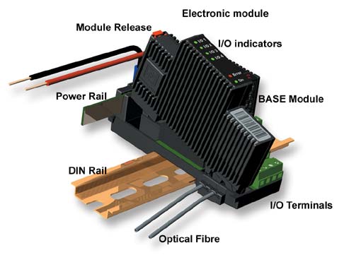
Mounting Modules and Forming ClustersThis section provides details of how to construct a cluster of modules. Module structurePD 600 series DPIs and I/O devices are made up of two parts – the Terminal Base Module and the Electronics Module.
|
|||||||||||||||||||||||||||||||||||||
|
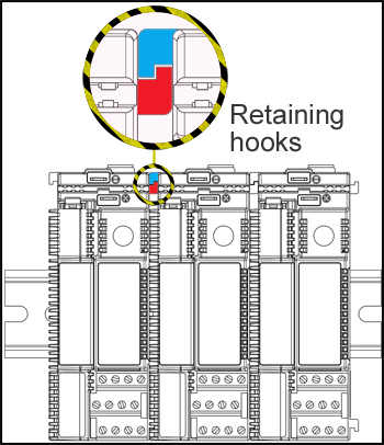
Additional base modules are fitted adjacent to one another, ensuring that the matching retaining hooks are engaged, as illustrated. This ensures that the four Light-Link communication windows in each module are correctly aligned. |
|
|
|
|
|
|
|
|
|
|
|
A cluster of distributed programmable and input and output devices normally includes at least one device which offers another P-NET interface in addition to Light-Link P-NET, to achieve communication with the rest of the system. One way is to include a “Simple P-NET Interface” module, which provides transparent RS485 P-NET communication between the rest of the system and individual modules via Light-Link P-NET. This configuration is especially suitable if no programmable control is to be included within the cluster. On the other hand, if programmable control is required, one or more DPI modules will be included, each of which offers a choice of interface capable of communicating using the P-NET protocol. If this method is used, the DPI will act as a gateway between the global P-NET sectors and local devices connected to Light-Link P-NET. |
|
|
 Having assembled and applied any user
labelling to the cluster, it is now ready to have external connections
applied. Input and output terminations have been designed to ensure that no
additional junctions or marshalling connections are necessary. In other
words, there is a single terminal available for each wire (refer to terminal
labelling), and there is no need to common up any signals. As far as applying
power to each module in the cluster is concerned, this is simply achieved by
fitting (pushing in) the appropriate length of supplied double-sided Power
Rail, into the aligned rear slots along the length of the cluster. Connection
to the actual power source (which might also be fitted to the DIN rail), is
made using any two of the spade terminals available along the length of the
cluster. Under normal operational conditions, the cluster power rail will be
retained quite satisfactorily. However, under high vibration and/or mobile
conditions, retention can be guaranteed by passing a 2.5mm cable tie through
the hole formed between the rail and the electronics module and clip around
the engaged inter-module retaining spigots.
Having assembled and applied any user
labelling to the cluster, it is now ready to have external connections
applied. Input and output terminations have been designed to ensure that no
additional junctions or marshalling connections are necessary. In other
words, there is a single terminal available for each wire (refer to terminal
labelling), and there is no need to common up any signals. As far as applying
power to each module in the cluster is concerned, this is simply achieved by
fitting (pushing in) the appropriate length of supplied double-sided Power
Rail, into the aligned rear slots along the length of the cluster. Connection
to the actual power source (which might also be fitted to the DIN rail), is
made using any two of the spade terminals available along the length of the
cluster. Under normal operational conditions, the cluster power rail will be
retained quite satisfactorily. However, under high vibration and/or mobile
conditions, retention can be guaranteed by passing a 2.5mm cable tie through
the hole formed between the rail and the electronics module and clip around
the engaged inter-module retaining spigots.
Light-Link
Light-Link is the means of communication between 600 series modules. The common Tx and Rx optical paths are automatically connected between terminal modules during placement, and an optical “spur” connection is made available to any electronics modules that are fitted. In copper wiring terms, using Light-Link is equivalent to daisy-chaining a 3-wire connection between each module, but without having to perform the time consuming and bulky physical connection. Such an optical medium obviously provides galvanic isolation, but since light signals are received, amplified and transmitted at each node junction (acting as a repeater), this ensures optimal Light-Link signal anywhere in a cluster of modules, no matter the number of modules.
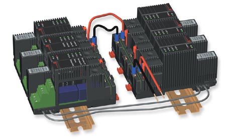
Linking blocks of clusters
|
It may
be more convenient to form a local cluster into two or more blocks, perhaps
in order to match with dimensions of a housing or
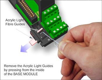
signal entry points. In this case, it is necessary to ensure that the
Light-Link communication path between modules is continuous. To achieve
this, two (or more) sub-clusters are linked together with two short pieces
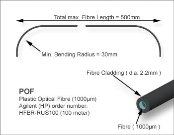
of polymer optical fibre (POF). First, the plastic light guide assembly in
each of the linked terminal modules has to be removed. This can be achieved
by first removing any electronic module, and then using an ordinary paper
clip to push the guide out. The POF cable type can be, for example,
Agilent Technologies type HFBR-RUS. |
|
|
|
|
|
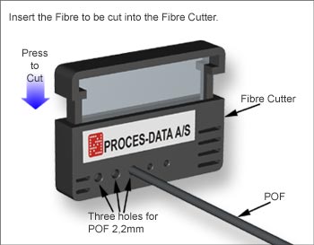
To ensure a clean interface, cut the
Polymer Optical Fibre (POF) to the length required, using the tool
illustrated below. |
|
|
|
|
|
In joining clusters together, the specifications provided below should not be exceeded. Note; Before going to the next step, please ensure that the POF has been properly cleaned, so that any remains of grease or oil on the surface have been removed. Otherwise the POF may not be properly fixed in the base module. |
|
|
|
|
|
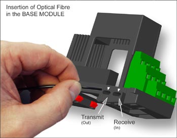
Next, the optical fibre is pushed into the hole until it is in line with the edge of the hole inside the base module. Now the electronics module is refitted. |
|
|
|
|
|
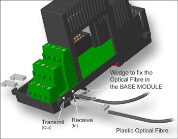
To ensure that the Optical Fibre is retained under all operational conditions, a holding wedge can be fitted. Note: The holding wedges are delivered in kits with short version wedges for left side mounting and long version wedges for right side mounting. Always use the proper version, depending on left or right side mounting. |
|
|
Power is linked between the sub-clusters using the most convenient spade connections. |
|
|
|