|
550 552 03 |
||||||||||||||||||||||||||||||||||||||||||||||||||||||||||||||||||||||||||||||||||||||||||||||||||||||||||||||||||||||||||||||||||||||||||||||||||||||||||||||||||||||||||||||||||||||||||||||||||||||||||||||||||||||||||||||||||||||||||||||||||||||||||||||||||||||||||||||||||||||||||||||
|
|
||||||||||||||||||||||||||||||||||||||||||||||||||||||||||||||||||||||||||||||||||||||||||||||||||||||||||||||||||||||||||||||||||||||||||||||||||||||||||||||||||||||||||||||||||||||||||||||||||||||||||||||||||||||||||||||||||||||||||||||||||||||||||||||||||||||||||||||||||||||||||||||
|
||||||||||||||||||||||||||||||||||||||||||||||||||||||||||||||||||||||||||||||||||||||||||||||||||||||||||||||||||||||||||||||||||||||||||||||||||||||||||||||||||||||||||||||||||||||||||||||||||||||||||||||||||||||||||||||||||||||||||||||||||||||||||||||||||||||||||||||||||||||||||||||
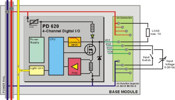 |
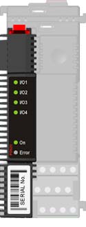
Channel Structure
The PD 620 consists of 5 channels as shown in then table.
|
Channel No. |
Channel Name |
Channel Description |
|
0 |
Device Ident.,Address and Config. |
|
|
1 |
General purpose Digital Input or Output |
|
|
2 |
General purpose Digital Input or Output |
|
|
3 |
General purpose Digital Input or Output |
|
|
4 |
General purpose Digital Input or Output |
Electrical Specifications
|
Power supply |
|
|
||
|
Power supply DC: |
Nom. min. max. |
24.0 V 18.0 V 32.0 V |
||
|
Ripple: |
max. |
5% |
||
|
|
|
|
||
|
Power consumption @ 24Vdc |
|
|
||
|
All outputs/inputs = ON |
max. |
45 mA |
||
|
All outputs/inputs = OFF |
max. |
30 mA |
||
|
Current requirement at power up: |
max. |
60 mA |
||
|
|
|
|
||
|
Digital Input |
|
|
||
|
Input voltage at ON: |
< |
3 V |
||
|
Input voltage at OFF: |
> |
9 V |
||
|
Input hysteresis: |
min. |
0.3 V |
||
|
Input current at ON: |
max. |
3.4 mA |
||
|
Input frequency: |
max. |
200 Hz |
||
|
|
|
|
||
|
|
|
|||
|
Start current (Duration max 2 sec.) |
max. |
2 A *) |
||
|
Load current at ON (Sink only) |
max. |
1 A |
||
|
Leak current at OFF |
max. |
500 μA |
||
|
Short circuit cutoff delaytime (current > 2 A) |
max. |
100 μsec |
||
|
Oneshot and Dutycycle resolution |
|
15.625 msec |
||
|
|
|
|
||
|
*) Enabled by setting MaxCurrent = 2 A, and MinMaxCurPreset = 2 seconds. By default, MaxCurrent = 1.0 and MinMaxCurTimer = 0.0.
|
||||
|
Load current measurements |
|
|
||
|
Accuracy: |
min. |
2.5 %, +/-10 mA |
||
|
Resolution: |
|
2.4 mA |
||
|
Repeatability: |
min. |
1 %, +/- 10 mA |
||
|
Current measurement update time: |
|
|
||
|
|
|
|
||
|
Analog Input |
|
|
||
|
Input voltage: |
0 - 15 V |
|||
|
Resolution: |
15 mV |
|
||
|
Voltage measurement update time: |
15.625 msec |
|||
|
|
|
|
||
|
Temperature |
|
|
||
|
Operating temperature |
-25 °C - 70 °C |
|||
|
Storage temperature |
-40 °C - 85 °C |
|||
|
|
|
|
||
|
Humidity |
|
|
||
|
Relative humidity: |
max. 95% |
|||
|
|
|
|
||
|
EMC |
|
|
||
|
EN 61000-6-2, EN 61000-6-3 |
|
|
||
|
|
|
|
||
|
Vibration |
|
|
||
|
Test method: IEC 60068-2-6 |
|
|
||
|
Frequency range: |
2-100 Hz |
|||
|
Frequency / amplitude: |
2-10 Hz : +/- 5.0 mm |
|||
|
|
10-100 Hz: +/- 2g |
|||
|
Sweep rate: |
max. 1 octave/min |
|||
|
Number of axes: |
3 mutually perpendicular |
|||
Mechanical Details
Related topics