|
550 739 01 |
||
|
|
||
|
Data Collect Configuration ProgramIntroductionThe Data Collect Configuration Program (DCConfig), provides a means to quickly set up and monitor a number of individual DataCollect Channels in a Data Collection enabled DPI (Datalogger, P-NET Controller). The data logged within DataCollect Channels is used by Visual VIGO to graphically display this in the form of curves and tables. Individual channels can also be configured and monitored using the property window of a Remote Data Acquisition component in Visual VIGO, but DCConfig provides the facilities to apply such activities to many channels at the same time. It also allows such configurations to be edited and stored on file, for immediate application to the same or additional controllers. The program is available as a licence free download.
Configuration and Monitoring TechniquesConfiguration PreparationThe program enables a systems designer to firstly prepare (edit) and then download (store) a set of configurations for up to 100 DataCollect channels. The designer can define the location of each log variable by PhysID, set logging threshold values, define sample times, and select and configure a range of conditional filters. Facilities are also provided to name particular filter conditions so that they can be quickly identified and selected to configure other channels. Each channel can also be identified with a comment. When editing is complete, this configuration set would be saved as a user named file.
Downloading ConfigurationsThe content of this file is now used to download (store) configuration data to the datalogger. The download mechanism first checks that there are no repeated log variable PhysIDs within the configuration file and that the settings defined for any thresholds etc. are legitimate. Next, channel numbers are allocated for each of the configurations, which are then downloaded.
Uploading DataAll of the channels configured as ‘active’ will now commence their data logging duties. This can be tested and monitored by using the ‘Load data from datalogger’ facility. This will provide values within the Channel Overview table in terms of channel number, current log value, sample timer, and decoded status information. This data can be updated by loading data again.
Uploading ConfigurationsFor Dataloggers that have already been configured, where the designer needs to be reminded of the current structure, or perhaps because additional channels need to be configured, the facility is provided to upload all configuration data from a selected datalogger. It is advisable to open a new configuration file before performing this procedure, since no user comments or user defined filter names are retained in a datalogger and will therefore be cleared from the table. To configure additional channels, or to reconfigure current settings, is a matter of adding additional rows in the table and defining the attributes. By selecting to download this configuration set to the datalogger, will allocate unused channels for the new configurations and, following a warning if you will be overwriting a currently configured channel, will download the data and start the logging activity. It should be noted that in modifying a currently active channel, any previously logged data could be lost. Data in current channels that are not being modified will not be affected.
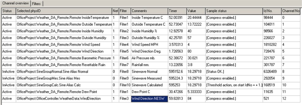
Program User InterfaceThe program is presented in the form of two tab-identified tables. The first is referred to as “Channel Overview” and the other as “Filters”. Channel Overview enables the user to see the configurations and latest data from all or a selected list of DataCollect channels. It also provides the ability to sort information by columns and to change the type of configuration (filter) and to activate/de-activate individual channels. The Filter table enables the user to define a set of named configurations (filters), which can then be applied to individual or groups of DataCollect channels. The program menu provides a number of general facilities such as saving files, inserting/deleting rows and up/downloading data to and from DataCollect channels.
Channel OverviewThis table consists of 10 columns, each having a particular attribute. Clicking on any of the column headings will perform a sort on the whole table with respect to that column, in either ascending or descending order. The width of columns can be adjusted by dragging the header boundary in either direction with the mouse.
StatusThis column indicates whether a particular channel is active or inactive. By clicking on an individual cell will toggle its present state.
Selected PhysIDThese cells show the actual Physical Identity of the variable to be logged in a DataCollect channel. Clicking on a particular PhysID or empty cell will highlight the cell and provide the opportunity to select a new one from the MIB.
NetThis editable column defines the network route through which the data-logging DPI can obtain the variable value. The syntax of this path definition is “[out of port No.][in through node address][out of port No.]…”. The node address of the final module is added automatically when downloading the configuration, so there is no need to include this. Net = 0 means that the value is obtained internally from within the data-logging DPI. For a PD 600L DPI, Port 1 is RS 485 and Port 2 is Light-Link. So, for example, if the variable to be logged is within a module in the local cluster, Net = 2. If the variable resides in a module directly connected to the same RS 485 network as the DPI, Net = 1. If Net = 2 5 1, it means the path is out of Port 2 (Light-Link), in through node address 5 (e.g. another DPI) and out of Port 1 (e.g. 485). According to the syntax there must be a space between each of the parameters defining the network route.
FilterThis column provides an indication as to the type of configuration that has been applied to this channel. The user has the opportunity (in the filter table) to give a meaningful name to each of the different configuration types. If a name has not been given, the program applies a default name such as “Unknown Filter 1…n”. Clicking on one of the cells in this column will provide a drop down list of all the configured filter types available, and the user may choose an alternative from these if required.
CommentsThis text column is freely editable by the user to provide some means of describing what function each channel provides e.g. “Tank 1 Temperature”. This data is only stored in the PC file, NOT in the datalogger.
TimerThese cells indicate the state of the logging timers at a particular point in time when data is uploaded. On performing a sort on this column, it can be easily seen whether any timers have gone negative or have not changed, indicating that there might be a problem with those particular channels.
ValueThis column contains the current value at the instant of data download of the variable that is being monitored for logging.
Sample StatusProvides an indication of how each channel is configured in terms of whether and what type of conditional processing is being applied.
Id No.Indicates the current identification number of the latest logged data at the time of data download.
Channel No.Identifies the channel number associated with a particular table row.
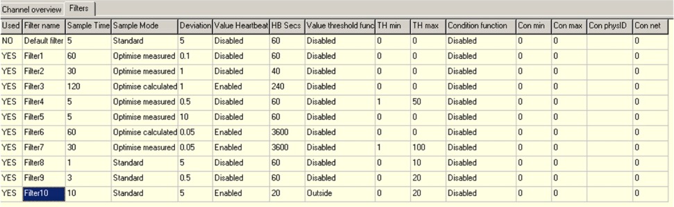
FiltersThe 15-column Filters table provides an easy way to define and apply a set of logging conditions to individual or to a set of DataCollect channels. By providing a meaningful name to each of the unique condition types, enables that log condition to be selected for particular log definition in the Channel Overview table. As with Channel Overview, each column width can be adjusted by dragging, and the first three columns can be sorted in ascending or descending order.
UsedProvides an indication as to whether this condition has been selected to be used by any log channel.
Filter NameThis editable column provides the means to uniquely name a condition filter. Thereafter, this name can be selected when configuring new channels.
Sample TimeThis editable column shows and provides the means to define the period in seconds between log samples applying this filter.
Sample ModeIndicates the kind of conditioning that is to be applied by this filter type. By clicking on a particular cell in this column and selecting the ‘+’ button, provides a pull down list to select the type of conditioning to be used.
· Optimise Measured – a means of data compression where only actual measured values that full outside a defined deviation tolerance are logged. See illustrated explanation. · Optimise Calculated – another means of data compression where a logged value is calculated when the measured value falls outside a defined deviation tolerance. See illustrated explanation. · Standard – all measured values are logged at sample time. See illustrated explanation. · Disable – Sampling is de-activated.
Deviation ToleranceProvides the means to define by how much a measured value must change either positively or negatively (deviate) before a new value is considered for logging. See fuller explanation.
Heartbeat FunctionProvides a pull down list to select whether this configuration includes the means to force a value to be logged if no conditional log values have been stored. See Heartbeat.
HB SecsThese editable cells enable a frequency to be defined at which a measured value is logged when no other logs have been taken during this period. See Heartbeat.
Value Threshold FunctionThe cells within this column include a pull down list providing a selection of conditional tests to establish whether a measured value should be considered for logging. See fuller explanation.
· Disabled – the Threshold Function is disabled and any measured value will be considered for logging. · Outside – Only measurements falling outside the defined Minimum and Maximum threshold values will be considered for logging. · Inside - Only measurements falling inside the defined Minimum and Maximum threshold values will be considered for logging. · Over - Only measurements exceeding the defined Maximum threshold value will be considered for logging. · Under - Only measurements falling below the defined Minimum threshold value will be considered for logging.
TH MinThese editable cells define the minimum or low value that will be used in the Threshold truth test.
TH MaxThese editable cells define the maximum or high value that will be used in the Threshold truth test.
Condition FunctionAn additional applied test to include the state of another defined secondary variable to establish whether the log variable is to be considered for logging. See fuller explanation.
· Disabled – the Sample Enable Function is disabled and will not influence the taking of log data. · Outside – Only when a secondary variable value falls outside the defined Minimum and Maximum values will log sampling be enabled. · Inside - Only when a secondary variable value falls inside the defined Minimum and Maximum values will log sampling be enabled. · Over - Only secondary variable values exceed the defined Maximum value will log sampling be enabled. · Under - Only secondary variable values falling below the defined Minimum value will log sampling be enabled.
Con MinUsed to define the minimum value used in the secondary variable test. Con MaxUsed to define the maximum value used in the secondary variable test.
Con PhysIDDefines the PhysID of the secondary variable. Clicking any cell provides the means to choose the required variable from the MIB.
Con NetThis editable column defines the network route through which the data-logging DPI can obtain the variable value for testing. For an explanation of the way this number is defined and used, see Net above.
Menu Items
File· New – Will open a new blank table. Provides a warning to save the current table if it has been changed. · Open – Provides a file selection window to open a previously saved configuration table. · Save – Save the changes made to the open configuration table using the current file name. · Save As – Saves the changes made to the open configuration table using a new name. · Config-file Info – Provides an editable dialogue box showing the file name and last edit date together with an area for users notes.
Edit· Delete channel-row (delete) – Deletes the row in which a cell is selected in the Channel Overview table. · Add channel-row (insert) – Adds a blank row to the bottom of the Channel Overview table. · Delete filter-row (delete) - Deletes the row in which a cell is selected in the Filter table. · Add filter-row (insert) - Adds a blank row to the bottom of the Filter table.
Datalogger· Select Datalogger – Provides a selection dialogue box with the opportunity to select a data logging enabled controller from the MIB. · Store configurations to Datalogger – Will download the configuration data from the currently opened file to the selected data-logging controller. A number of checks are made before this is performed:- o If a configuration file contains a repeated PhysID within the Channel Overview table, it will be prevented from being downloaded, and a warning given that “Two channels cannot have the same PhysID”. N.B. If it is necessary log a particular variable in different ways, create an alias to ensure that a PhysID is not repeated. o If one or more net definitions have not been entered, the configuration will be prevented from being downloaded, and a warning given that “A net must be chosen for all channels”. o If one or more status definitions (active/inactive), have not been entered, the configuration will be prevented from being downloaded, and a warning given that “All channels must be set to active or inactive”. o If one or more filter type definitions have not been entered, the configuration will be prevented from being downloaded, and a warning given that “A valid filter must be selected for all channels”. o If all the above tests are met correctly, a dialogue box asks “Are you sure you want to overwrite existing datalogger configurations?” By selecting “YES”, further checks are made to compare the configuration file with the current datalogger configuration. By selecting “NO”, no further download activity will take place. o If the configuration file to be downloaded does not define all the channels already configured in the datalogger, a message is given that “The datalogger contains one or more PhysIDs not included in the file you are storing. Do you wish to reset these channels?”. By answering “YES”, will delete those channels not included in the configuration file. Any newly specified PhysID will have a new channel created. All other specified channels will be unaffected. By answering “NO” will leave the unspecified channels unaffected during download. o If one or more currently configured datalogger channels’ PhyIDs are changed in the configuration file, the same message as above is displayed. By answering “YES”, will reconfigure those channels for the new PhyID and begin logging. The data collected by that channel using the previous PhysID will be lost. · Load configurations from Datalogger – Updates the table with the current configurations from the selected data-logging controller. Provides a choice of whether to load “All Channels”, “All Configurations”, or “Enabled Configurations”. N.B. Since a datalogger does not store any user comments or user filter names, uploaded configuration data will nullify any comments and show “Unknown” filter names in the currently opened file. · Load data from Datalogger – Provides a one-shot upload of the sample timers and the latest values at sample time (sample timer = 0). This can only be activated following the storing of configuration data from a previously saved file, or by loading configuration data into a new file. · Master Reset – Provides the ability to perform a master reset on the data-logging controller. This would normally only be performed when using a newly installed controller to which a prepared library of configurations are to be downloaded.
Memory· Memory Status – Provides a dialogue box containing information about how much memory is available on the PC hard disc together with how long it is possible not to have a Visual VIGO design running and connected before memory in the Data-logging controller starts to become overwritten.
Help· About – Shows information about the program and version · On-Line Help – Provides a link to the PROCES-DATA.com web site where this document can be found.
Related TopicsCollecting Remotely Logged Data Data Collect Configuration Program Download
|
|