|
551 432 01 |
|
|
|
|
PD 3950 Installation and Configuration (advanced solutions)
In certain situations, more than one PD 3950 may be required to be used. This document describes how to install and configure multiple PD 3950 devices on the same PC, and it also includes some helpful general hints.
|
|
|
Configuration of Larger Systems The easiest way to create a system with several PD 3950 modules is to import the pre-configured project that can be downloaded from our web site. It consists of two PD 3950 modules, each of them related to other modules on their P-NET ports.
Use the link Download page in order to download the workspace file ‘Multiple USB.vcf’. The file is zipped to protect it during downloading. Before it can be imported, it must therefore be unzipped to a relevant place on your computer.
In VIGO, use the normal procedure for importing and selecting a workspace.
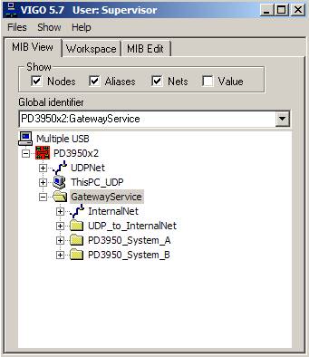
In the picture, three of the groups (folders) are shown in an unopened state, to give a better view. |
|
|
Each group (folder) contains the NeighbourNet that relates the other participants, the P-NET Gateway Service and the PD 3950 to each other.
The configuration corresponds with what is illustrated here and also principally with that shown in the document: P-NET Gateway Service Extended, except that the VIGO example project only has two groups of PD 3950 clusters.
The document referred to also explains about the components used to build up such a system.
IMPORTANT: Any new configuration involving changes related to the number of PD 3950 modules, requires that the P-NET Gateway Service configuration is run again. The configuration must be carried out before attempting to communicate with the modules. Refer to the section describing this issue.
|
|
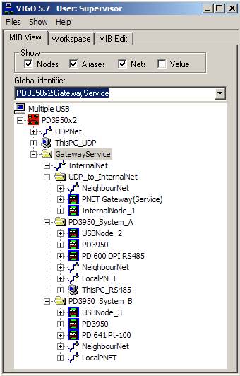
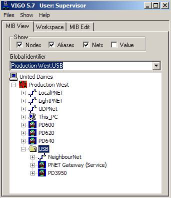
In the picture, the groups (folders) are shown in an opened state, which gives access to view all nodes in the system. The numbers in brackets in the following text refer to the illustration of the gateway service.
The group: UDP_to_InternalNet, consists of the components between the PC and the USB nodes of the PD 3950 clusters, namely the P-NET Gateway (20), the InternalNode (1), and the NeighbourNet connecting them to each other.
The group: PD3950_System_A, consists of the USBNode_2 (2) and one PD 3950. They are connected by means of a NeighbourNet. The P-NET side of the PD 3950 is connected to a PD 600 through the LocalPNET within that group.
The group: PD3950_System_B, consists of the USBNode_3 (3) and one PD 3950. They are connected by means of a NeighbourNet. The P-NET side of the PD 3950 is via a PD 661 connected to a PD 641 through the LocalPNET within that group. |
|
|
It should be noted that since the contents of the folders are independent of each other, the names and addresses used can be the same without causing any problems. As can be seen, this advantage has been utilized.
However, the nodes InternalNode, USBNode_2 and USBNode_3, must have unique node addresses, even though they reside in different groups, due to the fact that they are participants on the same net, the InternalNet.
So, keeping these rules in mind, the project can easily be expanded to cover, for example, five PD 3950 devices.
If, for instance, the group System_B is to be expanded into three more groups, simply copy the group itself and rename the new groups C, D and E.
The NeighbourNet, the LocalPNET, the PD 3950 and the PD 641 can be left unchanged with respect to names and node addresses, whereas the USBNodes must be renamed as well as assigning different node addresses between the existing participants on the InternalNet.
Of course, any requirements can be configured within the new groups, by, for example, adding various modules to the LocalPNet. |
|
Precautions When Connecting Nodes
When designing a system that includes several PD 3950 modules, each of them will be related to a specific part of the installation.
At the time when the modules are connected, it must be insured that this is actually the case. As illustrated in the example, the internal USB node 2 must be related to the PD 3950 for System A, node 3 to System B and so on.
This isn’t however, done automatically, and is why this aspect must be considered at this stage. If no relationship has been previously established, the first USB module that is being connected to a USB port, will automatically relate itself to the first available USB Node with the lowest number. |
|
|
There are two methods to avoid unintentional communication between USB Nodes and PD 3950 modules that are not associated with each other:
1) The module order is strictly kept during connection time, meaning that the PD 3950 for System A must be connected first, followed by the module for System B, etc. The serial numbers of the modules are not relevant in this case. The procedure requires a high degree of concentration, and there will exist a risk of an incorrect result, leading to erroneous communication.
2) The relationship between each USB Node and its matching PD 3950 module can also be made manually. If, for some reason, the relationship has initially been made wrongly, the procedure to correct this is the same as when establishing new relationships, except that any existing incorrect relationships must first be cancelled. A physical disconnection does not remove the relationship on the InternalNet.
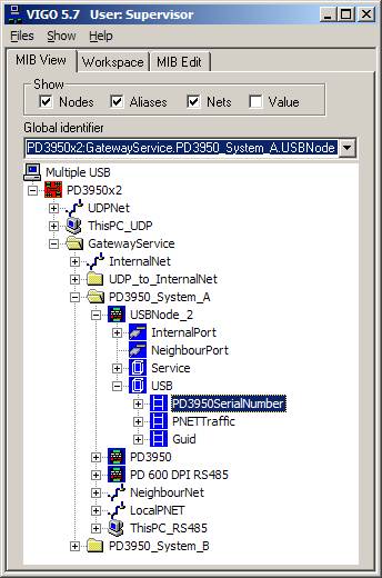
Follow this procedure to cancel existing relationships: · Physically remove the modules involved. The connection to the modules themselves will now be lost through this action. · However, the configured relationship between the USB Nodes and the physical PD 3950 modules will be retained. Use the VIGO Monitor, in which all instances of the USBNode_X.USB. PD3950SerialNumber are selected. Refer to the screen picture. · Remove any relationship between the USB Nodes and the involved PD 3950 modules by deleting the serial number in USBNode_X.USB. PD3950SerialNumber for each individual module |
|
Follow this procedure to establish or re-establish the relationships: · Do not physically connect any of the PD 3950 modules to the USB ports at this stage. · Use the VIGO Monitor, in which all instances of the USBNode_X.USB. PD3950SerialNumber are selected. Refer to the screen picture. · Establish a connection between each individual USB Node and the PD 3950, to which it is supposed to be related, by keying in the serial number of the PD 3950 module followed by the capital letters PD, e.g. 20041615PD. Do this in USBNode_X.USB. PD3950SerialNumber for each USB Node involved. · Physically connect all PD 3950 modules. · Use Set P-NET Node Address to set the node parameters on the P-NET side of the modules. · Communication can now be verified by monitoring any variable within the modules. · It should also be confirmed that the serial number entered for each module actually corresponds with that printed on the unit. |
|
|
IMPORTANT If, for some reason, the same PD 3950 serial number has been keyed in by mistake when relating a module to a USB node, the consequence is that none of the relationships will be established permanently. Each time the PD 3950 is initialized, either by connecting it or by powering up the computer, communication between the gateway service and the PD 3950 with that specific serial number will only take place if the program check verifies that such multiple use is not present.
This mechanism has been built into the program to prevent the risk of unintentional control and supervision of plant sections that are different from what the user is expecting.
|
|
Software Configuration
P-NET Gateway Service Editor
The default setting for VIGO is intended for simple PD 3950 communication. This means that if the application only involves one PD 3950, it is not necessary to run the Service Editor.
In cases where the gateway service, for some reason, is not running correctly, or if you need to reconfigure it due to the use of multiple devices, you should consult the P-NET Gateway Service configuration for further details of how to proceed.
When the gateway service is running correctly, the green On LED should be lit and the green Link LED should be flashing. Please consult the LED indicators for further details.
Once installed and correctly configured, the service starts automatically when the computer starts, so normally the user doesn’t have to be concerned about this. |
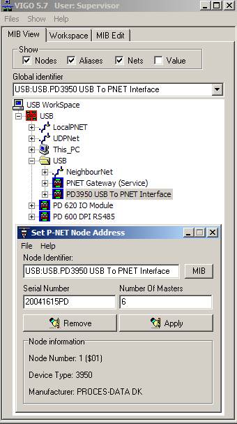
Setting the P-NET Node Address
Apart from setting up the service, the only other thing that must be done is to set the node address for the PD 3950 USB module, by following these instructions:
1) In MIB View, open the USB folder and right-click the PD 3950 module.
2) Use the Set P-NET Node Address utility to set the node address and the number of masters for the P-NET port.
3) Type in the serial number of the device.
4) Type in the number of masters. For the Local P-NET, the number of masters is 6 by default, so you must remember to change it according to the current application.
5) Click the Apply button in order to use the keyed-in values and establish contact with the module. The letters PD after the serial number are added automatically once the connection has been obtained.
If the project consists of additional modules connected to the PD 3950 (via the LocalPNET), they should now be within reach, using the Set P-NET Node Address utility for each of them. |
|
Expanding an Existing Project
If a larger and well-established system exists and works satisfactorily, you probably will not wish to recreate it in order just to introduce another method of communication.
On the other hand, an existing project can be changed in a way where, for example, a PD 3930 is just replaced by a PD 3950 and its related elements.
The following example differs from the one described previously in the PD 3950 single installation document, in which two projects were enabled at the same time. This example ends up with only one project, but additional effort must be used to reach a result.
|
|
|
Since the running project was probably based on a version of VIGO in which the PD 3950 and its related elements were not available, you will need to copy their types from the USB project to the project you are about to change.
To copy the types and make the relevant changes, follow these instructions:
Select the tab MIB Edit and choose the checkbox ‘Types’.
Open the USB project and select the two node types ‘PD3950_PC_USB_Interface’ and ‘UDPNode’, plus the two net types ‘Neighbour’ and ‘IP_v2’. The latter may be required if the original project was created with VIGO versions prior to 5.6. Hold down the CTRL key to select all of them before copying by means of the right-hand mouse key.
Open the existing project and use the right-hand mouse key function ‘Paste Sub’ to add the four types.
Add a group named USB.
Within the USB group, three elements with the following features for Kind / Name / Type must be added: * Net / NeighbourNet / Neighbour. * Node / PNET Gateway / UDPNode * Node / PD 3950 / PD3950_PC_USB_Interface.
Now, the new elements must be related to each other by means of the nets, and the existing VIGOPC net relationship must also be altered:
PNET Gateway UDPPort: Node Address 20; IP Address: 127.0.0.1:34380 (local host, port 34380).
PNET Gateway NeighbourPort: Net NeighbourNet; Node Address 0.
PD3950 PNET port: Net [whatever name previously used for the connection to the VIGOPC]. Node Address [whatever number previously used for the VIGOPC].
PD3950 PNET NeighbourPort: Net NeighbourNet; Node Address 0.
VIGOPC PNET ports must all be set to ‘none’.
VIGOPC IP_2 port must be related to net UDPNet; Node Address 99; IP Address [blank].
Outside the USB group, one element with the following features for Kind / Name / Type must be added: * Net / UDPNet / IP_v2
In the previous paragraph, a screen picture shows an existing configuration that has been expanded. The original configuration consisted of the devices VIGOPC, PD 600, PD 620, PD 640 and the nets LocalPNET and LightLink. |
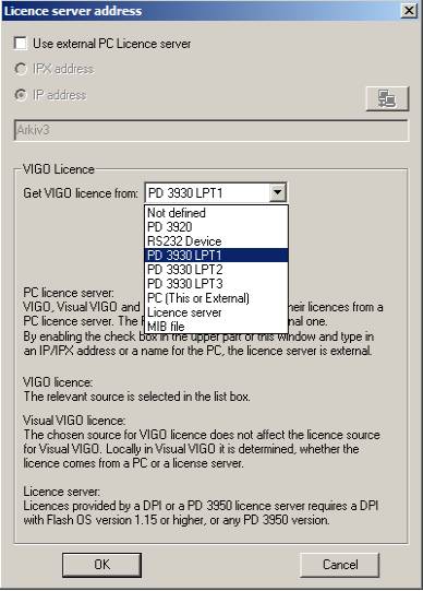
Licence Source
It must be remembered in any situation that the VIGO licence source has to be selected in accordance with the actual way of communicating.
It is handled in the pull-down menu Files \ Licence \ Licence Server, which leads you to the window illustrated next to this text.
The default setting of a new VIGO installation is that the option ‘Get VIGO licence from’ is set to ‘Not defined’, since VIGO doesn’t know anything about this.
The user must then choose from the list, which was opened at the time when this screen copy was made.
Licence server refers to PD 3950 as well as DPIs, since the structure of the licence channel is the same in both cases.
PD 3950 USB interfaces are factory preset with the licence information for VIGO, so no further steps need to be taken, unless of course a licence for Visual VIGO is also required. |
|
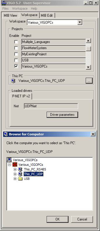
Configuration with various VIGO PCs
It may also be useful to expand your projects to cover several ways of communication. If, for example, the equipment is from time to time accessed by different people, i.e. people performing service or maintenance, this could be taken into account in the VIGO configuration. Perhaps one person uses a PD 3930 serial interface, and another person a PD 3950 USB interface.
A simple example is shown, just to illustrate this.
The PD 600 DPI can be accessed by a PC connected through a PD 3930 serial interface, as well as through the same PC communicating via a PD 3950 USB interface.
|
|
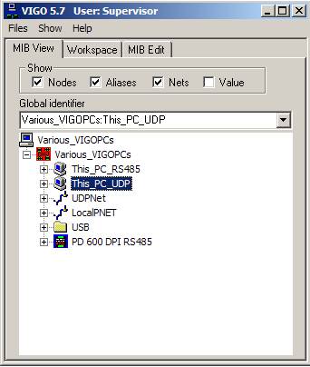
This_PC_RS485, as well as the P-NET side of the PD 3950, may have the same node address, since they are never connected simultaneously to the DPI.
Another necessary step to be undertaken prior to communication, is to select the relevant ‘This PC’ for the actual purpose, at least if the user swaps between the options. If the service person always uses the same way of communicating, this action can of course be omitted, since the VIGO configuration is located on his particular PC, and the settings have been saved since he was connected the last time. The screen copy shows the situation in which the previous ‘This PC’ was the one for PD 3950 communication via UDP, and where the user is now about to change this to the alternative PC.
Whenever this change is required and carried out, the user must remember to make yet another selection: The licence source, which was described previously, must be changed accordingly. Otherwise the error message ‘No VIGO Licence’ will appear, since the module containing the licence is no longer accessible.
|
|
Systems with Only One PD 3950This document has described how several PD 3950 USB interfaces can be installed and configured in new or existing projects.
However, how a configuration with only one PD 3950 USB interface is handled is also available. That description may also be useful for a basic and more general understanding of the PD 3950 connection concept. Use the link for single installation below. |
Related topicsP-NET Gateway Service configuration P-NET Gateway Service Extended LED indicators |
|