|
550 550 04
|
|
|
|
|
|
|
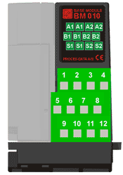
BM 010 seen from terminal side
|
Terminal
layout
|
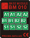
BM
010, top view
|
|
|
|
|
|
The BM 010 base provides connections for
devices with one P-NET RS485 channel, or with two independent P-NET RS485
channels.
Please note the following: When BM 010 is
used with devices with one P-NET RS485 channel, only the terminals marked A1,
B1 and S1 must be used. The terminals marked A2, B2 and S2 are reserved for
RS485 P-NET channel 2 on devices having two P-NET RS485 channels (PD 662).
|
|
|
|
|
|
Cable termination circuit
The BM 010 base module is equipped with
termination circuits for the two P‑NET channels.
It is recommended to enable the
termination circuit when the device is installed at the terminal ends of a
transmission cable. Enabling/disabling the termination circuit is done via
jumper settings.
|
Termination enabled:
|
When termination is enabled for P-NET 1
or P-NET 2 the terminals 2,6,10 and 4,8,12 are disconnected respectively.
This ensures that the termination can
only be selected at the end devices.
|
|
Termination
disabled:
|
The bus is
internally looped through from the first to the second terminal set. This
implies that incoming and outgoing P-NET cables have individual terminals.
|
|
|
|
|
|
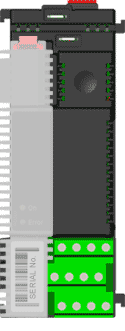
Jumper location
The jumpers
used to enable/disable the termination circuits are found on the printed
circuit board inside the BM 010, as seen on the picture.
J7 & J8: P-NET 1
J5 & J6: P-NET 2
|
|
Jumper
settings:
|
J8
|
|
J7
|
|
J6
|
J5
|
|
|
|
|
|

|
|
|
|
|
|
|
P-NET 1
P-NET 2
|
Termination disabled Termination
disabled
|
(Factory settings)
|
|
A
|
|
B
|
|
A
|
|
B
|
|
|
|
|
J8
|
|
J7
|
|
J6
|
J5
|
|
|
|
|
|
|
|
|

|
|
|
P-NET 1
P-NET 2
|
Termination disabled
Termination enabled
|
|
A
|
|
B
|
|
A
|
|
B
|
|
|
|
|
J8
|
|
J7
|
|
J6
|
J5
|
|
|
|
|
|
|
|
|
|
|
|
P-NET 1
P-NET 2
|
Termination enabled
Termination enabled
|
|
A
|
|
B
|
|
A
|
|
B
|
|
|
|
|
J8
|
|
J7
|
|
J6
|
J5
|
|
|
|
|
|
|
|
|
|
|
|
P-NET 1
P-NET 2
|
Termination enabled
Termination disabled
|
|
A
|
|
B
|
|
A
|
|
B
|
|
|
|
|
|
|
|
|
|
|
|
|
|
|
|
|
|
|
|
|
Specifications
|
|
|
|
|
|
Power supply
|
|
|
See the Specification for the
Electronic Module
|
|
|
|
|
Connector
|
|
|
Max. wire-dimension:
|
2,2 mm2
|
|
Cage clamp
opening size:
|
2.5 x 1.7 mm
|
|
Contact
resistance:
|
<15 mohm
|
|
|
|
|
Power Rail
|
|
|
Max. current
|
10 A
|
|
|
|
|
Ambient Temperature
|
|
|
Operating temperature:
|
-25 °C – 70 °C
|
|
Storage temperature:
|
-40 °C – 85 °C
|
|
|
|
|
Humidity
|
|
|
Relative humidity:
|
Max. 95%
|
|
|
|
|
Vibration approval
|
|
|
Standard:
|
IEC 60068-2-6
|
|
Frequency range:
|
2-100 Hz
|
|
Frequency / amplitude:
|
2-10 Hz: +/- 5.0 mm
|
|
|
10-100 Hz: +/- 2g
|
|
Sweep rate:
|
Max. 1 octave/min.
|
|
Number of axes:
|
3 mutually perpendicular
|
Related topics
Wiring diagrams
Base module overview
Ordering information
|
|
|
|
|
|
|