|
550 546 02 |
||||||||||||||||||||||||||||||||||||||||||||||||||||||||||||||||||||
|
|
||||||||||||||||||||||||||||||||||||||||||||||||||||||||||||||||||||
PD 662 P-NET Redundancy InterfaceGeneral information
The PD 662 P-NET Redundancy Interface is one of a number of standard modules within the PD 600 series range. Its main purpose is to provide a redundant and transparent link between optical Light-Link and a duplicated RS485 P-NET. The module frequently scans the RS485 communication links to check whether the communication networks are functioning correctly. The PD 662 will ensure that the local cluster of modules (i.e. the group of devices of which the PD 662 itself is a component), will receive data via one of the two RS485 P‑NET ports, and that data from the local cluster will be transmitted to both RS485 P‑NET ports. If, for example, P-NET port 1 is active, and a short circuit or a cable break is detected, the PD 662 will automatically switch to P-NET port 2. The module itself does not require any programming, but a P‑NET slave address and a few other parameters must be configured. The PD 662 is used with a BM 010 base module.
Redundancy System Block Schematic
PD 662 Block SchematicInternal structure and connection possibilities for a PD 662.
Channel structureThe PD 662 consists of 2 channels as shown in the table.
Communication interfacesThe PD 662 has two galvanically isolated RS485 P-NET interfaces, and one P‑NET Light-Link communication interface that is used for communicating with other locally mounted P‑NET devices using the optical Light-Link interface.
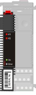
LED indicatorsThe module is equipped with four LED indicators: A green LED (On) to indicate that power is supplied to the module, a red (Error) to indicate internal errors within the module, and finally two red LED's (#1 and #2) to indicate whether RS485 Port 1 or RS485 Port 2 is currently reporting a malfunction. If none of these two red LEDs is ON, it indicates that both RS485 nets are in a fully functional condition.
Electrical Specifications
Mechanical Details
Related topics
|
||||||||||||||||||||||||||||||||||||||||||||||||||||||||||||||||||||