|
550 766 01 |
||
|
|
||
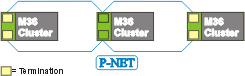
P-NET Redundancy:
P-NET redundancy provides an additional communication network path between a number of M36 clusters, where under normal operational conditions, one network is redundant. Each P-NET must be of the bus topology (terminated) type, maximum length 600 metres.
Each of the individual networks within a redundancy installation should be regarded in the same way as a traditional network, and follow the same rules as P-NET bus topology networks.
A redundant type network must only contain BM 010 base modules for mounting PD 662 electronic modules.
To achieve the full benefit of the redundancy network topology, the two P-NETs should follow different installation paths. This will help to prevent both P-NET cables being damaged during the same incident.
Termination:The BM 010 modules at the end of each network must be configured for termination. Mounting the BM 010 at the right most position in a cluster, it will allow easy access to the jumpers in the base module.
When the BM 010 is used as termination module the P-NET #1 must be connected to the 1'st terminal column from the left (terminals: 1,5,9), and P-NET #2 must be connected to the 3'rd column from the left (terminals: 3,7,11).
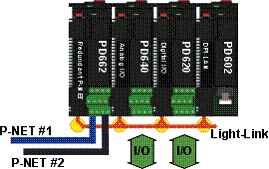
Wiring topics:
PD 662 cluster positionDue to the ability of the PD 662 to shutdown the Light-Link port if it detects errors in the port, it is recommended to position the PD 662 at one end of a DIN rail. This ensures that M36 modules will be connected only on one side of the PD 662 – see figure below. If the PD 662 is not placed at the end, it will not be possible to dismount the M36 modules next to the PD 662 without breaking the P-NET Light-Link communication, in the event that the PD 662 has shutdown the P-NET Light-Link port.
Recommended installation:
Related topics: |