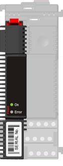
PD 640 Analogue I/O Module
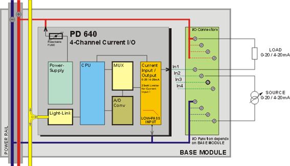
The PD 640 is a general-purpose analogue
I/O device with four I/O channels. Channel 1 and 2 may be configured for
either input or output. Channel 3 and 4 are input channels. All 4 channels
can be independently configured for either 0-20 mA or 4-20 mA signal types.
This enables most standard type analogue transmitters for pressure,
temperature, flow, etc., to be connected to the input channels, and, for
example, analogue actuators, motor controllers, etc, to be connected to the
output channels of the device. Conversion from or to 0/4–20 mA is performed
directly in the I/O channels, which means that process variables are read or
written in floating-point engineering units. For example, a process
controller or a PC can read the process value from a pressure transmitter,
which is connected to an input channel, in bar, kPa, psi, or any other
engineering unit, depending on the configuration.
PD 640 Block Schematic
Channel Structure
The PD 640 consists of 5 channels as
shown in the table.
|
Channel No.
|
Channel Name
|
Channel Description
|
|
0
|
Service
|
Device Ident.,Address and Config.
|
|
1
|
Analog_1
|
Analogue Input or Output
|
|
2
|
Analog_2
|
Analogue Input or Output
|
|
3
|
Analog_3
|
Analogue Input
|
|
4
|
Analog_4
|
Analogue Input
|
|
Power supply
|
|
Power supply DC:
|
Nom.
|
24.0 V
|
|
min.
|
18.0 V
|
|
max.
|
32.0 V
|
|
Ripple:
|
max.
|
5 %
|
|
|
|
|
|
Power consumption @ 24V DC
|
|
|
|
Operation:
|
max.
|
25 mA
|
|
Current at power up:
|
max.
|
60 mA
|
|
|
|
Analogue
input (Ch. 1-4)
|
|
Signal type:
|
Current (0 – 20 mA / 4 - 20 mA)
|
|
Calibration error:
|
@ Tamb. 20 °C
|
max. +/- 0.1 % of fullscale
|
|
Ambient temperature coefficient Tc:
|
max.
|
+/- 120 ppm / °C
|
|
Ambient temperature influence (ΔI):
|
Tc x (Tambient – 20) x Input
|
|
Resolution:
|
typ.
|
2 µA
|
|
Update time:
|
fixed
|
0.8 Second
|
|
Voltage drop across input at 20 mA:
|
nom.
|
1.2 V (60 Ω)
|
|
Current limiter (protection):
|
typ.
|
25 mA
|
|
|
|
Filter for analogue input signal
|
|
Type:
|
4th order low pass
|
|
|
Time constant:
|
configurable
|
3.0 s – 50.0 s
|
|
Gain error:
|
max.
|
+/- 0.1 %
|
|
|
|
Analogue output (Ch. 1 and 2)
|
|
Signal type:
|
Current (0 - 20 mA / 4 - 20 mA)
|
|
Calibration error:
|
@ Tamb. 20 °C
|
max.
|
+/- 0.25%
|
|
Ambient temperature coefficient Tc:
|
max.
|
+/- 160 ppm / °C
|
|
Ambient temperature influence (ΔI):
|
Tc x (Tambient – 20) x Setpoint
|
|
Resolution:
|
typ.
|
2 µA
(For firmware versions earlier than
103: 100 µA)
|
|
|
|
Ambient temperature
|
|
Operating:
|
-25 °C – 70 °C
|
|
|
Storage:
|
-40 °C – 85 °C
|
|
|
|
|
Humidity
|
|
Relative humidity:
|
max.
|
95 %
|
|
|
|
EMC
|
|
Immunity:
|
EN 61000-6-2
|
|
Emission:
|
EN 61000-6-3
|
|
|
|
Vibration
|
|
Test method:
|
IEC 60068-2-6
|
|
Frequency /
amplitude:
|
2-10 Hz: +/- 5.0 mm
|
|
10-100 Hz: +/- 2g
|
|
Sweep rate:
|
max. 1 octave/min
|
|
Number of axes:
|
3 mutually
perpendicular
|
|
|
|
|
|
|
|
|
|
|
Related topics
Ordering Information
Wiring diagrams
LED function
Base Module overview
Application notes
PD 641 Analogue Input Module
(Temperature)
PD 642 Analogue Input Module (mV /
Thermocouple)
|