|
551 377 01 |
|
||
|
|
|
||
|
PD 664 Configuration (GPRS)This document describes how the PD 664 can be configured for use as a gateway for P-NET communication via GPRS.
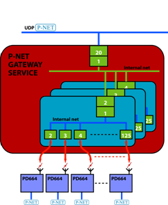
Configuring the PD 664 for P-NET communication via GPRS
|
||
|
The following equipment must be available:
Hardware· One or more PD 664 devices, including Base Module BM 010. · One antenna for each PD 664 device. · One SIM card for each PD 664 device.· The PC must have a P-NET interfacee.g. a PD 60x DPI (via a Ethernet or RS232 I/F), a PD 3950 (via a USB port) or a PD 3930 (via the parallel port).
Software· A PC with VIGO 5.7 or higher installed.
A Workspace in VIGO containing a minimum of two projects: A project used for PD 664 GPRS module configuration and a project used for GPRS communication.
· A MIB file describing the P-NET Gateway service configuration.
· A PC with the P-NET Gateway service software installed and it must have access to the Internet. Use this link to get more information about installation and requirements) for the Gateway Service.
|
|
|
|
When the above stipulations have been met, each PD 664 can be configured in the following way:
Hardware installation
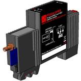
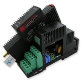
1) Install the SIM card in the PD 664. 2) Install the PD 664 in the BM 010 Base Module. 3) Connect the antenna to the antenna connector, and power up the device. 4) After power up, the Green ON LED will be lit and the Red Error LED may also be ON. This is a normal state, where this indicates a SIM card error due to a missing or incorrect PIN code. If the Red Error LED is flashing, it should be checked that the SIM card is inserted in the module correctly. 5) To ensure correct installation of the SIM card, it is recommended that the small lock adjacent to the SIM card slot is put into the lock position. If the SIM card needs to be replaced, then set the lock to the unlock position and press on the SIM card to release it.
|
|
||
|
|
|
||
Module configuration
1) Start VIGO and select the PD 664 node in the configuration project.
2) Use the Set P-NET Node Address utility to set the node address and number of masters for the P-NET port. Please note that the PD 664 is a master on P-NET Light-Link and must therefore be configured as a P-NET master.
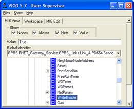
3) Use either the Monitor available in the right mouse menu or the value field in VIGO View to set Service.WriteEnable = True.
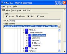
PIN code
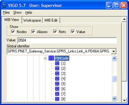
4) Select the variable GPRS.PINCode in the MIB and enter the PIN code associated with the inserted SIM Card. As soon as a valid PIN code has been entered, the Red Error LED will switch OFF. If no PIN Code is associated to the SIM card the Red Error LED will switch off as soon as the card is inserted in the module.
|
|
|
|
GPRS.ConnectionProfile
Please note that it may be necessary to contact the mobile service provider in order to obtain the correct settings for the four fields in GPRS.ConnectionProfile.
1) Select AccessPointName. in the event of a busy response, please wait a while until a value can be read. Write the name of the AccessPoint provided by your mobile service provider into AccessPointName. For example, AccessPointName = “internet” for these providers: TDC / Telmore /Sonofon / CBB. Username, password and DNSServer1 and DNSServer2 can be an empty string (blank).
2) Write the Username provided by your mobile service provider into the User field.
3) Write the Password provided by your mobile service provider into the Password field.
4) Write the IP address of the primary DNSServer provided by your mobile service provider into the DNSServer1 field. (Possibly might work without this information).
5) Write the IP address of the secondary DNSServer provided by your mobile service provider to the DNSServer2 field. (Possibly might work without this information).
|
|
|
|
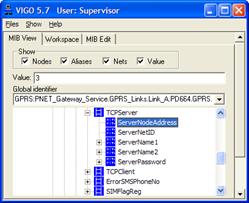
GPRS.TCPServer
1) Select the ServerNodeAddress and set it to the node number of the TCP node you want the current PD 664 to connect to. Look in the TCP node if in any doubt: “TCPNode.Service.PnetSerialNo.PnetNo”
2) Set the ServerNetID to value in “TCPNode.Service.NetID” The Gateway supports up to 15376 connections but if the configuration of the service only contain a single internal net (1-124 PD 664 ) the ServerNetID is always 255.
3) ServerName1 must point to the PC with the P‑NET Gateway
Service Installed. This can be an IP-address or a domain name, e.g. www.proces-data.com:34380 (default
port number). 4) ServerName2 (Optional). If you have entered a domain name above, you could enter the IP-address here.
5) This field holds the password used when connecting to the GPRS server. This field is "Write only". Password is a byte array of 16 bytes equal to 128 bits.
|
|
|
|
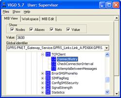
TCPClient
1) Point to ConnectRetryInterval in the GPRS channel: “GPRS.TCPClient.ConnectRetryInterval”Set ConnectRetryInterval to your preferred value. The default value is 3600 seconds = 1 hour.
2) Set CheckConnectionInterval to your preferred value. The default value is 600 seconds = 10 min.
3) Set AttemptsBetweenMessages to your preferred value. The default value is 20.
|
|
|
|
|
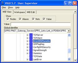
ErrorSMSPhoneNo
1) Point to PhoneNo in the GPRS channel: “GPRS.ErrorSMSPhoneNo”.
2) Set the PhoneNo to the mobile phone that should be notified via SMS, if the PD 664 is unable to establish a GPRS connection.
3) If a module disconnects and is not able to reconnect to the P-NET Gateway Service, an SMS message is sent to the ErrorSMSPhoneNo. There can be several reasons why a module can’t connect.
As soon as an ErrorSMSPhoneNo has been entered, is it advisable that the variables TCPClient.ConnectRetryInterval and AttemptsBetweenMessages are checked.
|
|
|
|
|
4) The module is now ready for use.
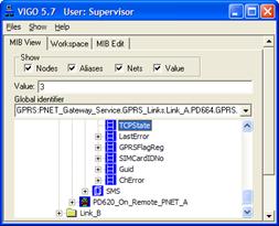
Connecting:
TCP state The TCPState variable can hold the following values: Initialising (0): The PD 664 has been reset. Offline (1): The PD 664 is not connected to the P‑NET Gateway Service. Connecting (2): The PD 664 is trying to connect to the P-NET Gateway Service. Connected (3): The TCP connection is idle, sending or receiving packets.
Link LEDOFF = Initialising ON = GPRS Connection, no trafficFlashing = GPRS Connection, traffic
Connecting to the P-NET Gateway Service If the PD 664 GPRS is not able to connect to the Gateway Service can the variable GPRS.LastError be very useful and consists of an ID number and a error text string. |
|
|
|
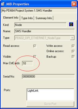
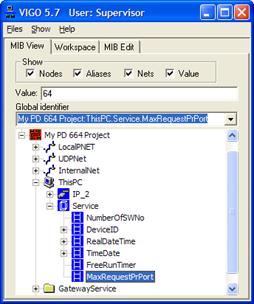
Tips and TricksThe transfer rate can be increased by adjusting Max. CtrlCards from 1 to 10 for all nodes accessed via the PD 664 GPRS Interface.
For “ThisPC”, the variable Service.MaxRequestPrPort can be set in the range 10-64. If the PC is communicating with several PD 664s, it would be an advantage to set this variable to 64, to increase the transfer rate.
|
|
|
|
Related topicsConfiguring the PD 664 for sending and receiving SMS messages.
|
|
||