|
551 495 01 |
|
||||||||||||||||||||||||
|
|
|
||||||||||||||||||||||||
The GPRS Project Tutorial
Phase 1 - Local Connection to the PD 664 and other modules Setting up the GPRS module for Cellular Operation Monitoring and Testing the GPRS Connection
Phase 2 - Setting up the Gateway Service Other setup requirements to enable the Gateway service. Setting up Port Forwarding in the Router
Phase 3 - Monitoring Remotely Located Clusters Using a PC on the local Gateway Service subnet Using a monitoring PC in another location Ensuring that P-NET data via the Internet is secure
Sending/Receiving an SMS from a Remote Cluster to/from a cellular phone
Dealing with SIM Cards and Service Providers Commissioning and Troubleshooting Tips and Tricks
IntroductionVIGO 5.7 has introduced some additional new items of hardware to the P-NET module range. One of these is particularly important in the area of remote process automation monitoring, because it enables P-NET communication to take place over the cellular wireless mobile telephone network (CellNet). Whilst it is already currently possible to connect two or more P-NET sub systems together via the Internet, or via two telephone modems, the former requires permanent wiring both ends, and the latter requires a reserved telephone line and connection time costs. Using the Internet and a particular aspect of communication provided by the mobile telephone network (GPRS), a permanent communication path can potentially be made, where charges only apply to the amount of data transferred. The PD 664 GPRS module enables a P-NET based system to be located in a place where an Internet or land line telephone connection is either not possible or uneconomic. This means that remotely located equipment can now also be monitored even if it is actively mobile.
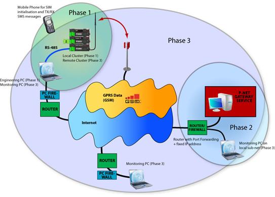
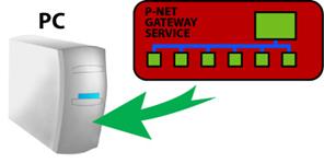
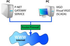
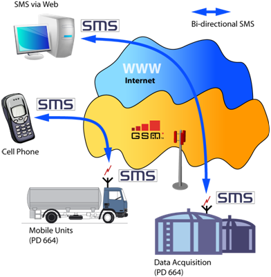
Three Steps to SuccessThe conceptual building blocks of a GPRS enabled system, where one or more remotely located processes or machines need to be monitored, can be thought of as consisting of three distinct parts. The first part is the operational system itself, consisting of a PD 664 module as the means of bridging the interface between the mobile phone network and the installed programmable controller/s and input/output devices. The second part is a PC or server based ‘Gateway’ located in another distant place, and designed to have point-to-point communication with one or more remotely located operational stations via the Internet and the mobile telephone network. The third part consists of one or more monitoring and/or data analysis stations, which again can be located anywhere throughout the world where access to the Internet is possible. These VIGO enabled PCs and SCADA monitors use point-to-point communication with the ‘Gateway’, which then routes data requests through to the required operational system.
Each of the three building blocks needs to be individually set up or configured in order to be able to intercommunicate with each other. Therefore, initially we need a means of being able to locally communicate with a PD 664 module in order to set various communication parameters, before this device, with others, is installed in a remote location (Phase 1). Next, we need to allocate and configure a PC or server that is to be utilised as the ‘Gateway Service’ (Phase 2). The reason for separate configuration scenarios may become clearer when it can be said that this ‘Gateway PC’ could be the same PC as that used to set up the PD 664 or it could be another one. It could also be a VIGO PC capable of monitoring remotely installed operational stations or purely used as a dedicated black box ‘Gateway Service’. Finally, we need to set up any PCs that are actually going to be used to monitor one or more of the remote operational systems (Phase 3). All these individual configurations can be done using a PC running VIGO 5.7 or higher, where the example GPRS project can be used on each PC involved with just a few individual changes to each. Once familiar with the concept, this project structure can be used as a template, and integrated into users’ own projects.
Conceptual diagram
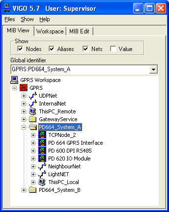
Phase 1 - Local Connection to the PD 664 and other modulesThe GPRS project has been structured so that there are two groups (systems) of modules defined, each of which could potentially be going to be installed at some distant location. However, initially they first need to be configured locally as physical clusters and therefore include a VIGO PC in each group. It is necessary for at least one VIGO PC to be defined and selected within an enabled project of a VIGO Workgroup, in order for the resident PC to be able to communicate with the outside world. As a default setting, the two ‘Local PCs’ have been declared for communicating via a PD 3930 parallel port. The fact that a PD 664 mounted on a BM 010 base module also acts as a ‘Simple P-NET Interface’, means that virtual direct connection to the GPRS module’s Light-Link port can be made without needing access through a DPI port. For laptop users without parallel ports, this could also be achieved using a PD 3950 USB/ P-NET module The reason that two groups of modules have been included in this example project, is to show that a monitoring/engineering PC can be in communication with more than one remotely located system at the same time. The user is, of course, at liberty to reconfigure the template project in any way to suit and reflect the type and make-up of a system for experiment or real use. However, unless the local cluster/s and communication interfaces are exactly as defined in the example GPRS project, it is advisable to copy and rename this project, to avoid overwriting it during any future VIGO upgrade.
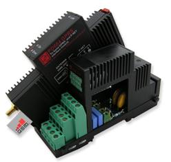
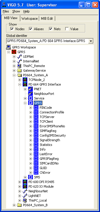
Setting up the GPRS module for Cellular OperationThe PD 664 has a GPRS channel, which for this part of the exercise is the focus of attention (together with part of the Service channel). Here is the means for setting up the previously obtained and enabled telephone service provider’s SIM card, so that communication can occur on the cellular wireless network. It also provides the means to define the specific interface between the Internet and the P-NET Gateway Service used for routing signals from monitoring/management PCs. It should be realised that no configuration can take place without a suitable SIM card being inserted into its slot on the module. See the section on SIM cards.
|
|||||||||||||||||||||||||
PincodeThis register holds an up to 8 characters code, which is compared with a PIN code held on the SIM card when it is inserted or powered up. If comparison is not met will cause the Red error light to flash. More often than not, the default PIN on the SIM card is also 0000. If the PIN on the card is not active, then this register has no effect. Pincode
ConnectionProfileThis record contains information that will be written and stored on the SIM card. It should be noted that Service.WriteEnable should be set True while making any changes, and that a module reset must be made when all configuration is completed (Service.Reset = 255). The information to be written will be provided by the Cellular Network provider. This can normally be obtained by referring to the provider’s web site or by contacting their customer services. The details vary widely from service provider to provider, where some don’t require Username and/or Password to be defined, and others use variations depending whether your subscription to the service is on a Pay as you Go (PAYG) or monthly paid annual contract basis. It is very important to realise that if any of the entries are incorrect, no connection will be achieved on this first of a number of steps that need to be made. ConnectionProfile
§ AccessPointName:Known as the ‘APN’ and often identifies the provider, e.g. “internet”, “mobile.o2.co.uk”, “orangeinternet”.
§ Username:Varies with provider, but can sometimes be left blank, e.g. “mobileweb”, “user”.
§ Password:Varies with provider, but can sometimes be left blank, e.g. “password”, “pass”.
TCPServerThis record deals with identifying the Gateway in terms of its location on the internet, and the TCP node address that will be used when routing P-NET requests to this eventually isolated cluster of modules.
§ ServerNodeAddress:This could be an exclusive number between 1 and 125, and must correspond with the TCP node Number that has, or will be, defined within the Gateway Service for this particular communications path.
§ ServerNetID:Unless the Gateway Server is to be used to route more than 125 individual paths, this value will always be 255.
§ ServerName1:This defines the full Internet identity of the Gateway Server. This can be in the form of an IP address and port number, or a URL and port number. e.g. “217.198.219.98:34380” or http://your_company.com:34380. Except in special circumstances, the port number will always be 34380, since this is one of the recognised TCP/UDP port numbers for P-NET IP communication. The other reserved port of 34381 is for secure communication using UDP. It should be realised that the IP address is the external address of the ADSL router to which the Gateway Server PC is connected, NOT the local address of the PC itself. See later about what needs to be done about ‘port forwarding’ in the router.
§ ServerName2:This also defines the full Internet identity of the same or an alternative Gateway Server. For example, ServerName1 could use the URL of the server, and ServerName2 could define the less descriptive IP address. If, for some reason, the translation from URL to IP address fails within the Dynamic Name Server (DNS), the PD 664 will use the alternative form to make contact with the cellular ‘phone provider. Alternatively, and just as relevant, the Name1 could be identifying one server as a URL or IP, and Name2 could identify a completely different server. This provides a certain degree of redundancy should this part of the external network path ever exhibit a problem.
§ ServerPassword:See GPRS Channel description.
TCPClientThis record determines how the GPRS module maintains the connection with the cellular service provider.
§ ConnectRetryInterval:The factory default value for this register is 3600 seconds (1 hour). For the purposes of initial set up and test, it is advisable to set this to say 30 (half a minute), otherwise it will take up to an hour to re-establish a connection after a drop out. The reason for a longer period during normal operation is that there is a connection overhead (data), which if the gateway service is not contactable for a period for some reason, will continue to accumulate chargeable data at each attempt. § CheckConnectionInterval:See description § AttemptsBetweenMessages:See description
Monitoring and Testing the GPRS ConnectionThere are a number of registers available to ensure that the link with the mobile phone provider has been configured correctly and has been established. First ensure, following a module reset, that all the settings in the Connection Profile record have been retained (stored on the SIM card). If these registers are monitored immediately after a reset, they will indicate ‘Too Busy’ for a few seconds during the writing and reading process, and will then show the data that had previously been configured.
Signal StrengthCheck that SignalStrength is at least at a higher level than 10 to ensure reliable and continuous communication with the provider. If the gateway that was specified is running, then the Link light should now illuminate to show that a path has been established from the PD 664 through the telephone provider’s wireless-to-Internet router, through the port forwarded configured router associated with the gateway PC and through the Gateway PC firewall. If the gateway has not yet been configured, the only way to test whether a path exists between the PD 664 and the mobile phone company, is to send out or receive in an SMS message (Sending/Receiving an SMS).
StatisticsThe two registers within this record indicate the actual amount of P-NET data transfered. If this remains at zero after a reset, or is not accumulating, it is an indication that the route to the gateway service has not yet been made.
InfoThis record holds various information that can be useful in analysing the status of a connection.
§ TCPState:Shows a value from 0 – 3, where 2 shows that attempts are being made to connect to the gateway service and 3 indicates that connection has been established (synonymous with Link light).
§ IPAddress:If indicated, is the address allocated by the CellNet provider, but is only provided when the link with the Gateway service has been established.
§ LastError:This record can provide helpful information on what is causing a connection with the CellNet provider not to be possible OR what the last error state was before the link with the gateway was established. See GPRS Channel description in the data sheet for details of all the error states.
For a more general description of GPRS Channel configuration, PD 664 Configuration (GPRS)
Phase 2 - Setting up the Gateway Service
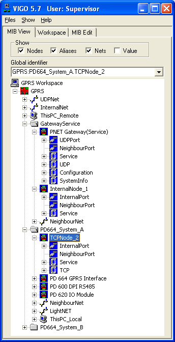
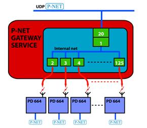
The P-NET Gateway Service is a piece of software which runs as a service in the background on a Windows based PC. It is designed to route IP type packets containing P-NET messages between two ports, one or both of which will be connected via the Internet. In the case of the GPRS project, it is configured to accept P-NET requests from separate local or externally located monitoring PCs via a UDP port, and switch the route to one of possibly many TCP ports that are connected via the Internet and the mobile phone network to GPRS enabled P-NET modules. For the purposes of this tutorial, we will be describing the Gateway Service as being set up on an independent PC (or server) having access to the Internet, and initially at least, will also be running with VIGO. However, the user should also understand the role this Gateway Service PC/Server is going to play in terms of its position within an overall system network structure. This could vary between a simple system using a general purpose PC with a Windows firewall and an ADSL router, to one using a dedicated server within a corporate network, involving proprietary software/hardware firewalls and NAT routers.
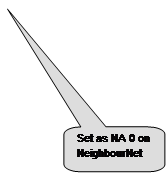
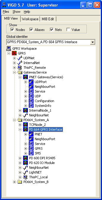
UDPNodeUnder the ‘Gateway Service’ group, a UDP node is included. When the default Net ‘UDPNet’ has been selected in UDPPport properties, this port has a required node address of 20 and also holds the user defined local IP address of the gateway together with a port No. (socket). e.g. 192.168.1.4:34380 or 127.0.0.1:34380 (local host). N.B. It should be ensured that the local IP address is fixed within the operational sub-net and not allocated automatically via DHCP. This is achieved within the TCP/IP properties window of the Local Area Network Connection. Except in special circumstances, the port number will always be either 34380 or 34381 (secure), since these are the recognised IP port numbers for P-NET traffic. The remaining port in this node is called NeighbourPort. This has been configured in NeighbourPort properties to be associated with a pre-defined net type called NeighbourNet. NodeAddress is not defined (default zero
InternalNodeThis declared node provides the link between UDP traffic and TCP traffic entering and exiting the Gateway Service. Again, when the default ‘InternalNet’ has been selected in InternalPort properties, this port has the required node address of 1. The remaining port in this node is called NeighbourPort. This has been configured in NeighbourPort properties to be associated with a predefined net type called NeighbourNet. Node address is not defined (default zero).
TCPNodeEvery TCP node declared in a project is associated with a single piece of remotely located operational equipment that includes a PD 664 GPRS module. In the GPRS project, two such nodes are included for familiarisation with the concept of remote monitoring, and can be seen here individually grouped with two clusters of P-NET modules. When the default ‘InternalNet’ has been selected in InternalPort properties, this port has a requirement for a unique node address to be configured that hasn’t yet been used elsewhere e.g between 2 and 125. Here, node numbers have been configured as 2 and 3 respectively, which reflects the TCPServer.ServerNodeAddress already configured in a PD 664 module.
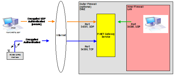
Other setup requirements to enable the Gateway service.As indicated above, secure access to and from the Internet will also require settings to be made in the network environment’s firewall/s and router/s. Since such hardware/software configurations can be quite complex, especially within a corporate environment where perhaps local ‘monitoring’ PCs are also involved, we can only discuss the bear essentials. For this purpose, we will assume that the Gateway PC will use the built in Windows firewall and that a standard ADSL router will be utilised. However in most situations, this should provide sufficient information for IT managers or systems administrators to apply these setting requirements to their own networks.
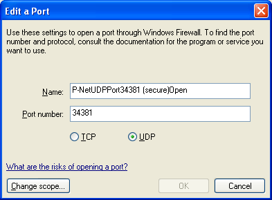
Gateway PC FirewallIt is quite usual for the default security settings of a Windows based PC to block any incoming traffic that isn’t associated with installed common communication applications such as Internet browsers and Email clients, and/or to prevent communication between machines outside the local area network. If application programs are to provide a service (server) to clients on the Internet, it will be necessary to define some exceptions to indicate to the firewall that incoming traffic associated with a particular application is permitted through. This is commonly done by opening a port recognised by the communicating application, to permit communication to occur. Since the P-NET Gateway is a communications server, it is therefore a requirement to open a couple of recognised ports to enable the transport of P-NET messages. In the case of the personal firewall provided with Windows, this is achieved by opening the ‘Windows Firewall’ from the ‘Control Panel. Select the ‘Exceptions’ tab and click the ‘Add Port’ button. Choose UDP and type a meaningful name e.g. “P-NET UDP Port”. Then enter 34380 as the Port number. Repeat this process to add Port No. 34381 for use when the secure key enabled form of P-NET communication is to be used. Finally, open the TCP port No. 34380 for use by messages between PD 664 GPRS modules and the Gateway service
If there are alternative or additional hardware/software firewalls between the Gateway PC/Server and the Internet, these ports will also need to be opened. Example:
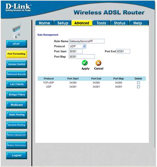
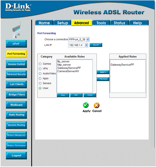
Setting up Port Forwarding in the RouterThe connection between the Gateway PC and the Internet will be via an ADSL (broadband) router continuously connected to an Internet Service Provider (ISP). The connection between the PC/Server and the router can be via Ethernet cable or wireless. It is recommended that such a router is allocated a fixed world-wide internet address by the ISP with possibly an associated URL. This is because a static IP address within each PD 664 GPRS module has to be configured. (N.B. It is possible to use a dynamically allocated variable IP address, but this would mean using a service such as that offered by dynDNS.org, and then only using the defined URL in a PD 664). In order to ensure that the router will allow any traffic that contains the address of the Internet side of the router through to the Gateway PC, it is necessary to arrange to identify the Gateway by means of a port number. This technique is known as ‘Port Forwarding’ and this facility must be available for configuration within the router. Each make of router will have slightly different ways of setting this up, so reference should be made to the manufactures’ user manual. In a similar way to ‘opening’ a port in the Windows and/or other Firewall, the port forwarding configuration consists of defining that for a given port number ‘attached’ to the IP address or URL i.e. ‘:34380’, this traffic should be ‘forwarded’ to a static local IP address e.g. 192.168.1.4. Again, the particular IP protocol also needs defining, which in this case is 34380 and 34381 for UDP ports, and 34380 as a TCP port.
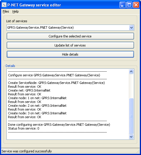
Configuring the ServiceNow that the required structure for the Gateway service for this particular project has been completed in VIGO, and that ‘This PC’ in the Workspace Tab is “This PC_Remote” in the GPRS project, it should now be possible to configure and run the service for use locally and via the Internet. Run the program “P-NET Gateway Service Editor” from the All Programs|PROCES-DATA|P-NET Gateway Service menu. From the list of services, select the one marked GPRS:GatewayService.PNET Gateway(Service). Now click the “Configure the Selected Service”. If all entries have been correctly configured in VIGO, the result should be displayed in the editor in a similar fashion to that shown below. If this service has been configured before, a window will warn of the existence of a previous configuration and ask whether it’s OK to overwrite this.
The ‘editor’ is showing that the Gateway Service ‘nodes’ defined within the current VIGO project have been created internally and that their port attached ‘nets’ have been interconnected to route data within this software gateway.
If the ‘editor’ indicates that there is ‘no response’, ‘no route to net’ and/or ‘timeout’, this could be due to the fact that the wrong Workspace or incorrect VIGO PC has been selected (it must be an IPv2 net type, connected to UDPNet). It could also mean that the encrypted key enabled UDP security utility has been enabled but is incorrectly configured. If this might be the case, unencrypted communication can be enabled within the ‘Key Manager’ – General tab. Configuring for encrypted communication is discussed later. Now that the Gateway Service seems to be configured and running, this can be visually confirmed by selecting each of the Gateway modules in turn and checking that the FreeRunTimer (FRT) in each of the Service Channels is incrementing.
The Gateway Service PC together with its associated Internet router, is intended to be running at all times, to enable monitoring PCs to be able to communicate with possibly many PD 664 enabled operational clusters at any time. This is why it would not be unusual to have a dedicated PC specifically allocated to perform this task. If the gateway service is stopped, or the gateway PC is switched off, then each remotely located operational cluster will attempt to reconnect at set intervals as defined in the PD 664 GPRS channel: TCPClient.ConnectRetryInterval. This is likely to invoke an accumulating minimum GPRS connection charge overhead, which otherwise would not be necessary if the service is always available
Phase 3 - Monitoring Remotely Located Clusters
Using the Gateway Service PCOnce all configuration has been completed and the Gateway Service started, it should be possible to see that the Link light on a ‘remote’ PD 644 has become illuminated. Since the Gateway service was also set up using the GPRS VIGO project, it should also now be possible to directly communicate with a remote cluster from the Gateway PC. The best way to initially ‘look’ into the cluster, is to monitor the FreeRunTimer (FRT) in the GPRS module Service channel.
Using a PC on the local Gateway Service subnet
Using a monitoring PC in another locationOne or a number of other PCs running VIGO with access to the Internet can, from any world location also monitor the Gateway and any number (<125) of remotely located systems. In this case again, the IP address defined in the UDPNode UDP port should be changed to that of the fixed global Internet address of the Gateway, e.g. 84.92.226.169:34380. This configuration achieves the ultimate target of the distributed GPRS system, but unlike the other connections described above, requires that routers and firewalls to have also been configured correctly. Firstly test the connection with FreeRunTimers in the Gateway PC/Server. Then connect with the GPRS module FRT. Note that initial connection with a variable may take up to the time defined in TCPClient.ConnectRetryInterval in the GPRS channel of the PD 664 module. If either of these communication paths do not seem to be working, use the tests described in Commissioning and Troubleshooting Tips and Tricks.
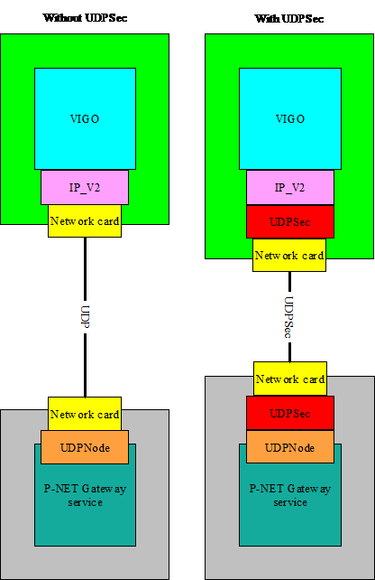
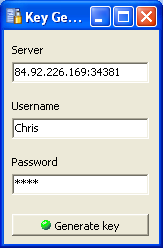
Ensuring that P-NET data via the Internet is secureWhilst TCP packet data between the Gateway Service and a PD 664 GPRS module is already encrypted, P-NET UDP data between a monitoring PC and the Gateway Service is not in a standard (port 34380) configuration. This may not be particularly important if the monitoring PC is on the same local network as the Gateway PC or server and behind a firewall. However, to ensure that such data can be made secure for any client-server situation, two utility programs are available. These are the ‘Key Manager’ and the ‘Key Generator’ and are found in the ‘PROCES-DATA’ program folder, under ‘P-NET Gateway Service’.
Key ManagerThe method of encryption using the UDP communication through port 34381 is achieved by means of a generated ‘key’. The user of the client or monitoring PC will be informed as to what the global IP address of the Gateway service is, a user name and a password, all of which is, initially at least, declared using the Key Manager in the Gateway PC.
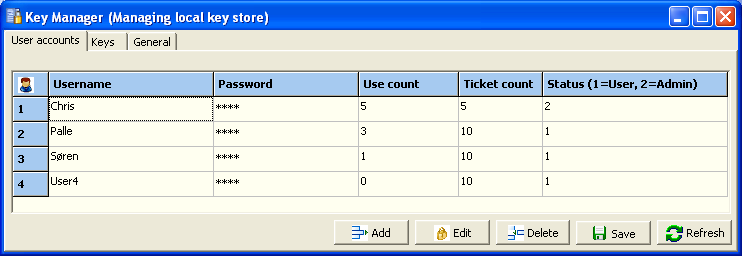
User accounts SørenAs many user names and passwords can be declared (Add) that are required (Save). Each could be associated with the owner of a supervisory or monitoring PC, or may be associated with a person dealing with a number of PCs. Such a person would likely have the Status of Admin (2). After entry, passwords are hidden, but can be highlighted again (edited) by first clicking a password field and then clicking again. The Use count column will eventually show how many times a particular Username and Password has been used to generate a new key. The Ticket count is a manual entry (default 10), defining how many keys this user is allowed to generate.
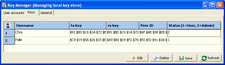
KeysThis page shows how many keys have been generated by a particular user together with the name or address of the machine that generated it.
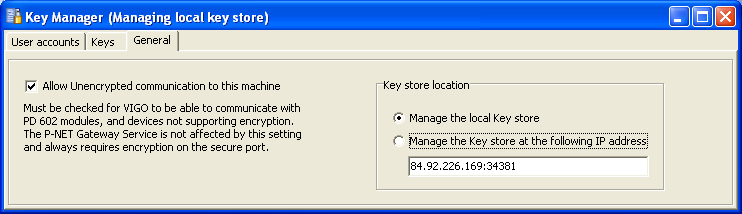
GeneralThis page is important in determining whether the Key Manager is being operated from within the Gateway PC, or from a remote location manned by an administrator. If management (and key storage) is being performed from within the Gateway PC, then the manager will be configured to operate locally, probably “localhost:34381”. However, for an operator with admin status it is also possible to manage the key store from a remote location. This can only be done from a remote PC that has already successfully generated and stored a key in the Gateway PC. Assuming that this is the case, the Key Manager in the remote PC should have the “Manage the key store at the following IP address” radio button checked. The address and secure port No. should be added to the address field. If this entry is successful (i.e. the Internet path to the Gateway PC router is open, the port forwarding is correctly set, the firewall is open for port 34381 and the key has already been generated), the User accounts and Keys pages will be a facsimile of the entries that are already entered using the Key Manager on the Gateway PC. This means that editing and additional entries can be performed from a remote location. If the connection cannot be made, then an error message will be shown.
Key Generator
Sending/Receiving an SMS from a Remote Cluster to/from a cellular phone
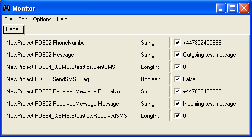
One of the most useful advantages of using GPRS facilities within a P-NET project, is that the PD 664 module, together with some system software, is capable of sending (and receiving) SMS text messages. One of the most obvious uses for this ability is for sending alarm event messages to one or more cellular mobile phones. To form the required data structure of an output SMS text message and to decode a received message, a small piece of additional software is required to be running on a DPI within the operational system cluster. In order to provide a simple means to test this facility, a small skeleton program is available for download from the PROCES-DATA.com web site. Used together with a running Monitor display, will enable a user to define a telephone number, a text message and a ‘send’ switch for sending out a message, and also seeing a received message from a specific telephone.
Such a test program can be very useful during initial development and commissioning of a GPRS system to ensure that a good connection is being made between the mobile phone service provider and the eventual remotely located operational system. The principles can then be integrated into the system software for alarm monitoring, and perhaps the use of decoded received messages to perform a particular system function, with an acknowledge message being returned.
Depending on the particular type and address of DPI being used, all that is required to be changed before compilation and download, is the declaration of port and node address to suit the cluster under test Further information about the configuration of the PD 664 for SMS and sample Process Pascal routines for the sending and receiving messages can be found in the document Configuring the PD 664 for sending and receiving SMS messages
The point is, that unlike buying a telephone in a shop, which will, by means of the included SIM card, be allied to a particular service provider, a PD 664 GPRS module is not delivered with a SIM card, thereby enabling the user to purchase one from the provider of choice, together with arranging the most convenient method of payment for the service. Now, there may be a local service provider who will sell one or more contract or PAYG SIM cards, and ensure they are already ‘switched on’ for GPRS before delivery. However, the vast number of SIM cards available, either purchased in a shop or on-line, requires that the initial set up registration to be adhered to. Although in essence the PD 664 is a tri-band mobile telephone, its structure is such that it doesn’t have an individual keyboard or display. This means that if a hand-shaking procedure is required to enable GPRS, it may be a good idea to have an ‘ordinary’ telephone available just for going through this initialisation process. Apart from setting up the provider’s database record, nothing is written to the SIM card at this stage. It is only when the SIM card is inserted in the PD 644 module that specific configuration data is actually written to it.
It may sound obvious, but it is important to choose a provider that is local (national) to the system which includes the GPRS module. In other words, if the operational system is to be located at a weather station in Egypt, it wouldn’t be a particularly good idea to subscribe to a Danish provider, otherwise the charges involved will be at the ‘International Roaming’ rate!
On the subject of charges, in choosing your provider, consider carefully the method of payment. All providers charge for the amount of data transferred, not the time connected. However, some offer unlimited data transfer per week for a set monthly fee, others offer a maximum daily charge on PAYG if you transfer more that a few ‘web pages’ of data, others just a straight ‘so much per MB’. It should also be recognised that there is a minimum overhead in terms of data transfer when initially making a connection between the PD 664 and the Gateway service. It should therefore be ensured that unless purposeful disconnection is made during certain parts of the day, that the signal strength and or reliability of a continuous connection should be checked, otherwise an unexpected run out of a PAYG subscription may occur, even though no meaningful data may have been transferred.
With PAYG, practically all providers will enable you to monitor and top up your subscription on-line, without needing to touch the remotely located SIM card.
Commissioning and Troubleshooting Tips and TricksThe fact that this extremely versatile method of monitoring remotely located equipment from number of individual monitoring points, means that sometimes one of the communication paths or node interfaces may not be appear to be working properly. To make it easier to analyse where a problem may lie, a few tips may be found to be useful in pin-pointing the cause. Apart from a mobile phone, the ‘test equipment’ used are utilities or applications available on a PC.
§ PINGPING (Packet InterNet Grouper) is general networking tool available from the Command Prompt. It sends out a test packet to the defined IP address or URL, which is echoed back and the round trip time measured together with a report of any missed packets. It is very useful in establishing the path from a remote PC to the router of the Gateway Service. N.B. The router must be configured to allow pinging (ICMP).
§ TelnetTelnet is a TCP/IP protocol used for communicating commands between computers. It is also the name of client software used to write commands and receive data. Normally, a log in and password process is required when communicating with equipment which supports external network management, but we are using it in its simplest form to just confirm connection with the Gateway Service through the routers and firewalls. Again, this utility is available from the Command Prompt.
§ Internet BrowserThe use of an internet browser e.g. Windows Internet Explorer, will, as a minimum confirm that connection with the Internet is possible, and that any internal firewalls and routers are operational.
§ Mobile PhoneThe use of a test or operational mobile phone may prove useful in initially establishing a GPRS service with a provider. Later, this may be defined as the unit to receive SMS alarms/reports from remotely located systems and/or to send test or encoded SMS commands.
§ Local monitoring the Gateway ServiceIf the PC can communicate with the Gateway service, it should be able to see the FreeRunTimer (FRT) of the UDPNode (marked P-NET Gateway(Service) in the GPRS project). If not:
§ Remote Monitoring PC to Gateway ServiceIf the monitor PC can communicate with the Gateway service, it should be able to see the FreeRunTimer (FRT) of the UDPNode (marked P-NET Gateway(Service) in the GPRS project). If not: § Check that the Monitoring PC has a path to the Internet using, for example, Internet Explorer.
§ Check using the Command Prompt that you can ‘Ping’ the Internet address of the Gateway Service’s router. E.g. “ping 84.92.226.169”.
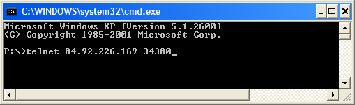
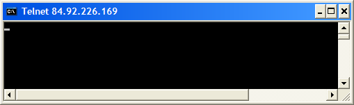
§ Check that the appropriate ports are open (port forwarding and firewall exception rules) using Telnet. E.g.” telnet 84.92.226.169 34380”. If operational, it should look like the attached screen. If any random characters appear in series, it indicates a break and re-established service. This telnet session can be closed down by inputting multiple characters until the command prompt is shown again. It should be noted that Telnet is only a protocol within TCP packets, so a problem with UDP would not be highlighted.
If none of these tests have been able ascertain the problem, it is highly likely to be a problem within the Gateway system.
§ Checking the Gateway Service systemThe Telnet check using a PC from another Internet location is a useful way to confirm the operation of:
§ The port forwarding of ports 34380 to the local IP address of the Gateway PC within the Internet router and
§ The port enable exceptions within any firewalls shielding the Gateway PC.
§ Check that the static IP address of the Internet Router publicised for use by PD 664 modules and monitoring PCs is correct by using an Internet Browser on the Gateway PC and addressing “http://www.myip.dk ”. This will give the IP address and URL, if allocated.
§ Each of the pseudo gateway service modules has a Service Channel, within each of which is a FreeRunTimer. Each of these can be useful monitors from both outside via the Internet and internally within the Gateway service to check the serviceability of interconnection.
§ Checking the GPRS connection
§ During configuration of a GPRS module, a simple way to check that a connection is being made with the cellular phone service provider, is to send a module an SMS message, while monitoring the SMS channel e.g. PD664.SMS.Statistics.ReceivedSMS.
§ During commissioning, run the simple test program described previously to send and receive SMS messages.
§ During remote operation, it is worth considering the incorporation of an engineering test routine, where the decoding of a particular received SMS triggers a return SMS to be sent back in response.
Related TopicsIntroduction to the PD 664 P-NET GPRS Interface
Configuring the PD 664 for P-NET communication via GPRS Configuring the PD 664 for sending and receiving SMS messages
PD 663 Simple P-NET Interface Triple Speed
Info notes Communication with VIGO from a DPI through a P-NET Gateway Service Communication with a PD 6xx module from a PD 602 through a P-NET Gateway service Communication from a DPI to DPI through a P-NET Gateway Service
|
|||||||||||||||||||||||||
|
|
|||||||||||||||||||||||||